
CNC Machining Common Materials
By: Jonathan Siddoway
The MAKE studio has a ShopBot Desktop Max CNC Machine. CNC machines are incredibly useful for creating parts with very precise tolerances. This allows for making a near infinite amount of designs. However, CNC machines are inherently dangerous and require great accuracy during design to function. This blog will help teach how to be safe while using CNC and general rules of thumb to make cutting your designs a breeze.
First lets talk about how a CNC Machine works. In order for the machine to cut into our material, it uses a cutter, which it spins at incredible speeds and moves across the material, slowly cutting out our design. CNC is an acronym which means “Computer Numerical Control” simply meaning that all the movements of the machine are created by a computer reading numbers. These numbers are in a form called “G-Code” We won’t go into depth on how G-Code works in this blog, but if you want to know, I recommend this article to begin.
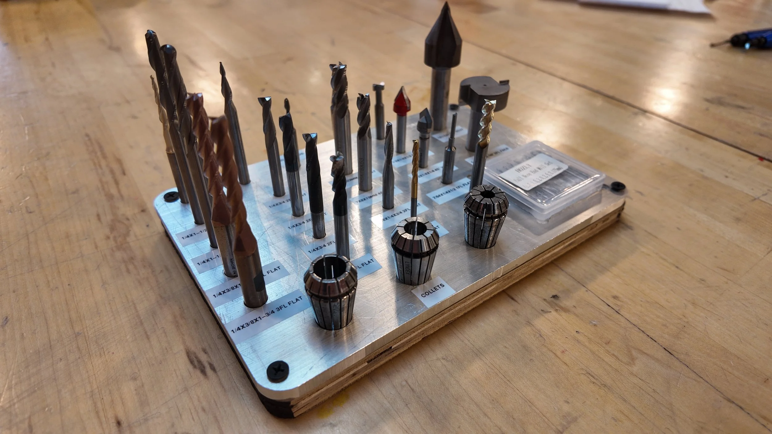
CNC Machining has many important pieces, but the most important part to understand is the Endmills. Endmills look very similar to drill bits and are used to cut our material.
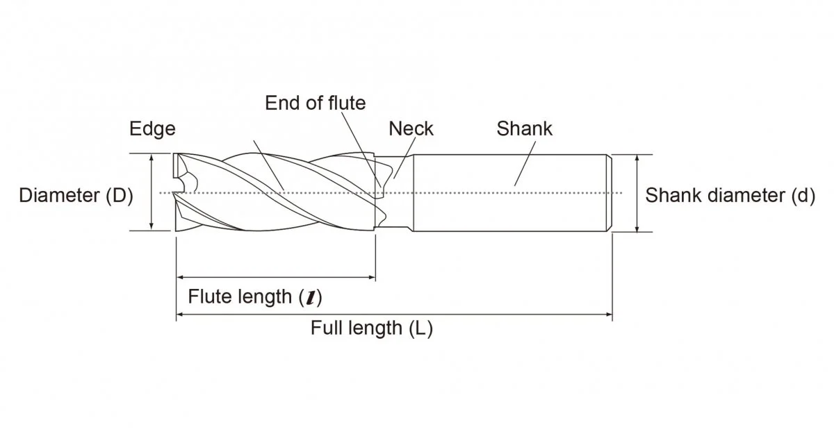
Image Credit to SpeedTiger
There are three main things to look for when choosing which Endmill to use.
1) Endmill/Cutter Diameter (⌀)
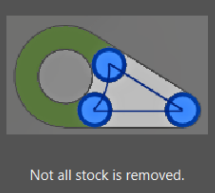
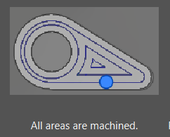
This is the diameter of the cutting edge (labeled Diameter in diagram above). When Cutting , you will typically want the largest endmill that can accurately cut out your design. Notice in the pictures below that the large endmill cannot fully cut out the shape while the smaller endmill can fit between the inner and outer circle. Image credit: Autodesk Fusion 360
2) Number of Flutes
The flutes on an endmill are the actual cutting faces on the Endmill. The number of flutes determines a few very important properties. The first property is tool strength. Simply put, the more flutes an Endmill has, the stronger the Endmill is structurally. There is a diagram below showing how as Flute count increases, the thickness of the “core” increases, meaning the endmill is more durable and can cut stronger materials.
This comes at a tradeoff of chip evacuation. While the machine is cutting into the material, it needs a place for the newly cut off “chips” to go. Endmills are made (typically) with an upward spiral to eject the chips upwards and away from the material. With less flutes, there is more space for the new chips to leave the endmill.
Tip: 3 Flutes is a good middle ground for chip evacuation and tool toughness
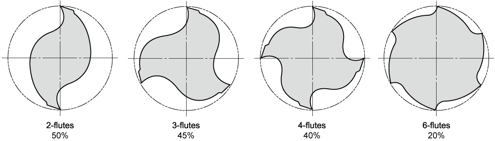
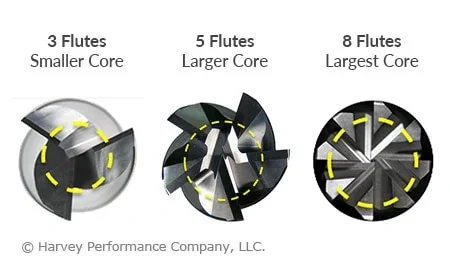
Image Credit: BestEndmills & HarveyPerfomance
3) Length of Cut (LOC)
Length of Cut is how long the cutters go up the Endmill - otherwise known as flute length - and it determines the maximum depth at which the endmill can cut. That being said, just because you can use the full LOC (length of cut) doesn’t mean you should. The amount of tool engagement (how much of the tool is touching the material while cutting) changes the speeds and feeds that you can cut with.
It is standard practice that the depth of cut (how far down the Endmill goes into the material) should be half the Endmill’s Diameter. That being said, to increase the Endmills lifetime and our safety, we typically run about 20% of the tool’s diameter. ex: 1/4” endmill can cut 1/8” deep into the material at a time
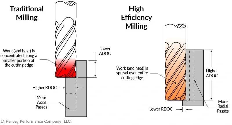
A time that you can use deeper cuts is for Side Milling, which is where you begin cutting from the side of the material or a premade hole/pocket. This means only the side of the tool is touching the material and by extension, the wear is more evenly dispersed. There are many benefits to this laid out by Harvey Performance in This Article and image below.
While on the topic of side milling, now is a good time to talk about the different types of cuts. Generally, there are 3 types of cuts: Slotting, Roughing, and finishing.
Slotting: Full tool engagement with the material
Roughing (Side Milling): Tool enters an existing pocket and quickly moves sideways to remove chips with a large depth of cut.
Finishing: Same as roughing, but less material is removed leaving a cleaner finish.
SPEEDS AND FEEDS
This is a very large topic, and also an important one. So lets get into it.
Speeds and Feeds control how fast the Endmill is spinning and moving through the material. Getting the Speeds and Feeds wrong is the cause of most problems, including (but not limited to) Tool Chipping, Tool Breaking, Tool Wear, Chattering, Gantry seizing, and poor surface finishes.
Knowing this, the next question is: How do we get it right?
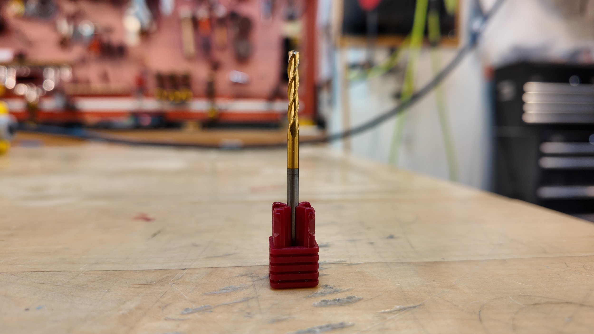
Simply put, it’s complicated. So I’m going to walk you through Speeds and Feeds with a 1/8” Endmill we have here at JUMP.
First let’s talk about what we’re looking for.
Cutting / Surface Speed: How fast the Endmill moves across the surface of the workpiece. Calculated in “Surface Feet Per Minute” or “SFM”
Spindle Speed: How fast the machine will spin the Endmill. Calculated in “Rotations per Minute” or “RPM”
Feed / Feed Rate: How much material will be removed. Calculated in “Inches per Minute” or “IPM”
Feed per Tooth: How much material is removed by each individual tooth / flute on the endmill per revolution. Calculated in “Inches per Tooth” or “IPT”
Manufacturer Specifications
The best place to begin is the Manufacturer Specifications.
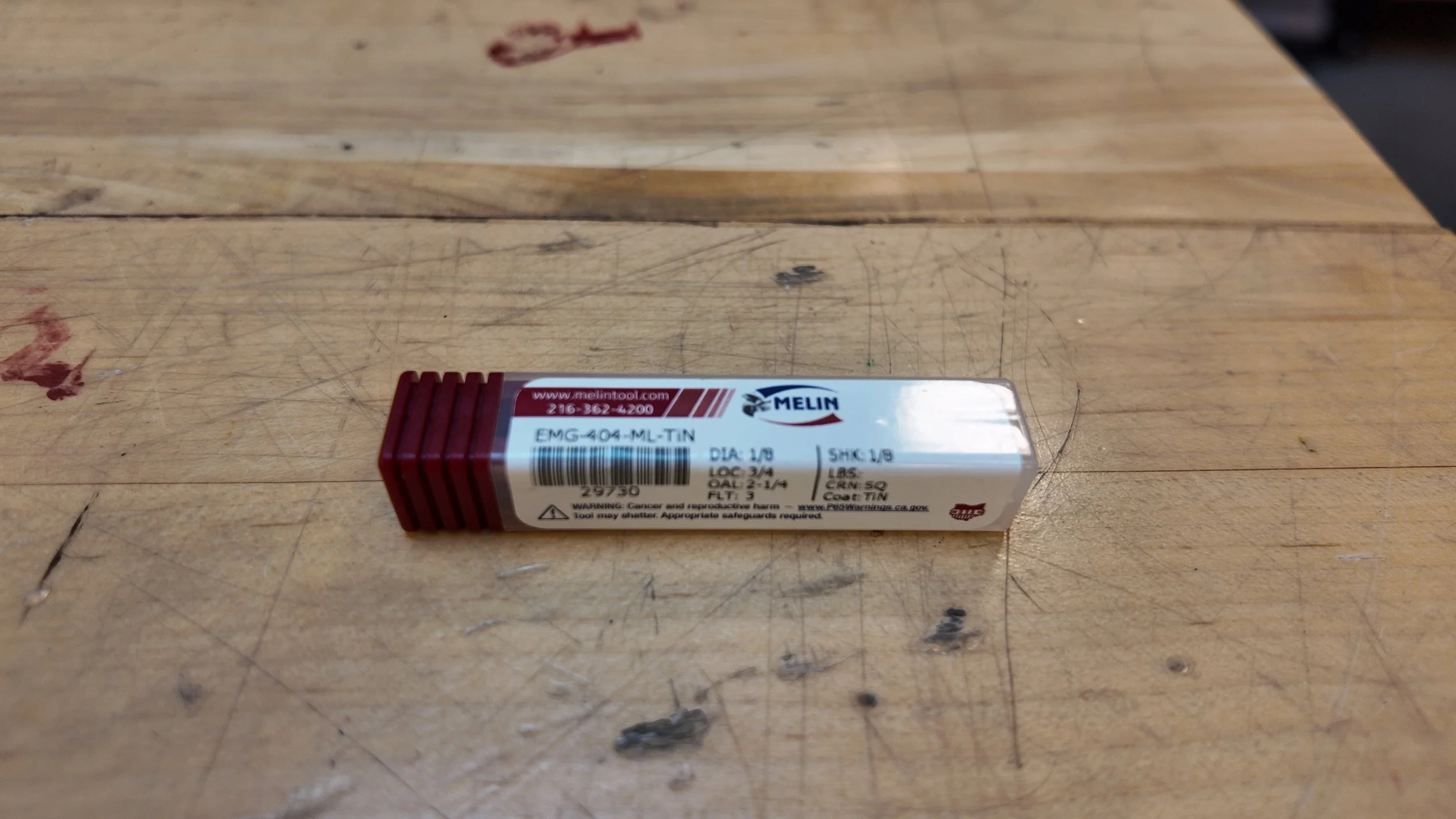
You will need to know the company that made the endmill in order to get the manufacturer specifications, and in our case, the Endmill we have is a Melin 1/8” flat endmill.
Note: If you do not know the company that made your endmill, there is a generic sheet at the bottom of this section.
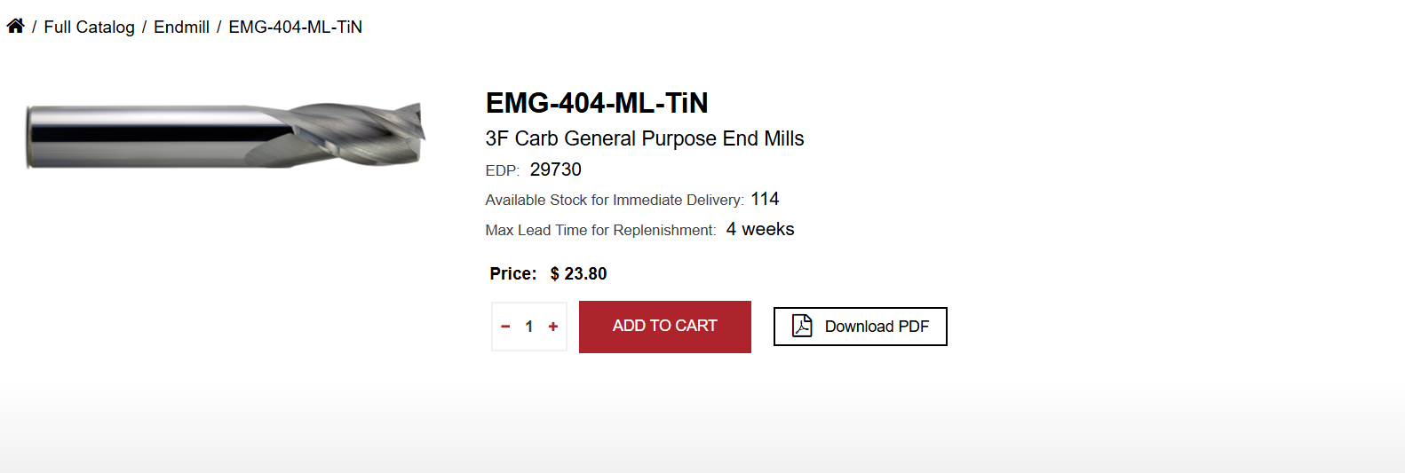
Finding the endmill on the website does not bring us to the feeds and speeds recommendations so Instead we should search for it directly.
Searching “Melin manufacturer speeds and feeds recommendations” will bring us to their database where we can find our tool again.
When we find our tool again, it brings us to a pdf spreadsheet containing the information we need. That being said, learning to read these specification sheets can be confusing.
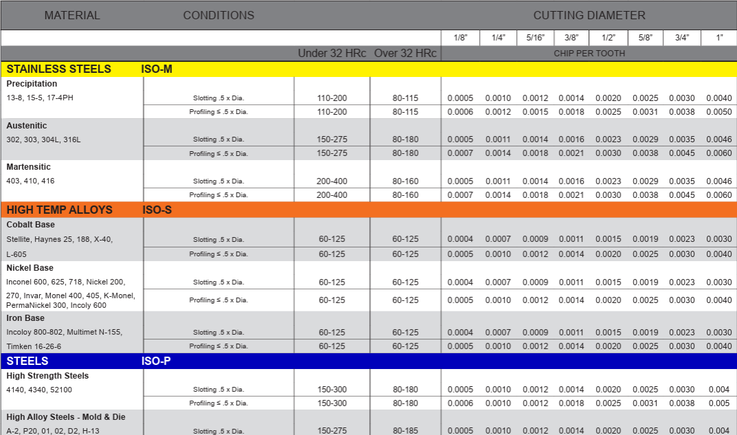
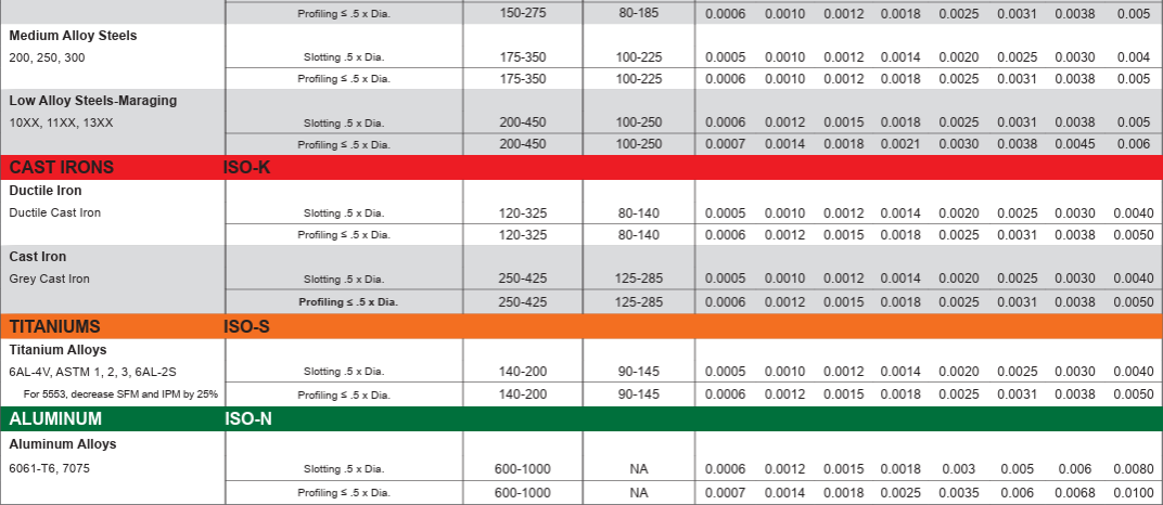
The furthest left column on the graph is materials. For this example, lets choose Aluminum. The second row over labeled “conditions” is the type of cuts we are doing. Lets use the Slotting setting because we expect to cut out pockets using the full tool. (profiling is the roughing and finishing cuts)
The 3rd and 4th column is the Cutting Speed. The 32 HRc label refers to the Rockwell Hardness chart, which simply put, is how hard a material is. Aluminum is soft and therefore has only one option. The chart gives us a range of 600-1000 SFM.
Finally the last column is how much material each flute (also known as teeth) will cut off at a time. Following the 1/8” cutting diameter column down, we see that our feed per tooth is .0006” IPT.
With this, we can begin calculating for everything else!
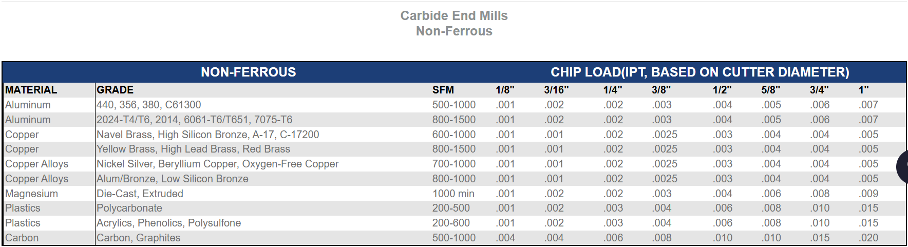
If you cannot find manufacturer specs, this chart is a useful guide. Credit: HarveyTool
EQUATIONS
**NOTE: The Equations for Imperial and Metric are DIFFERENT. Make sure you are using the correct one!
These are the equations we will use for Imperial Units:
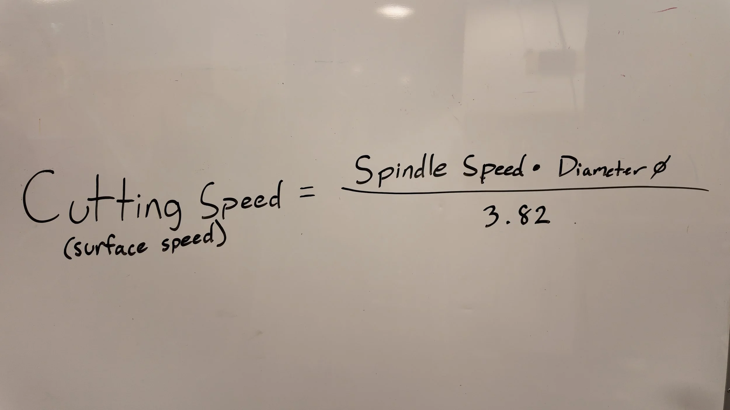
Surface Speed (SFM): (RPM x Diameter) ÷ 3.82
Spindle Speed (RPM): (SFM x 3.82) ÷ Diameter
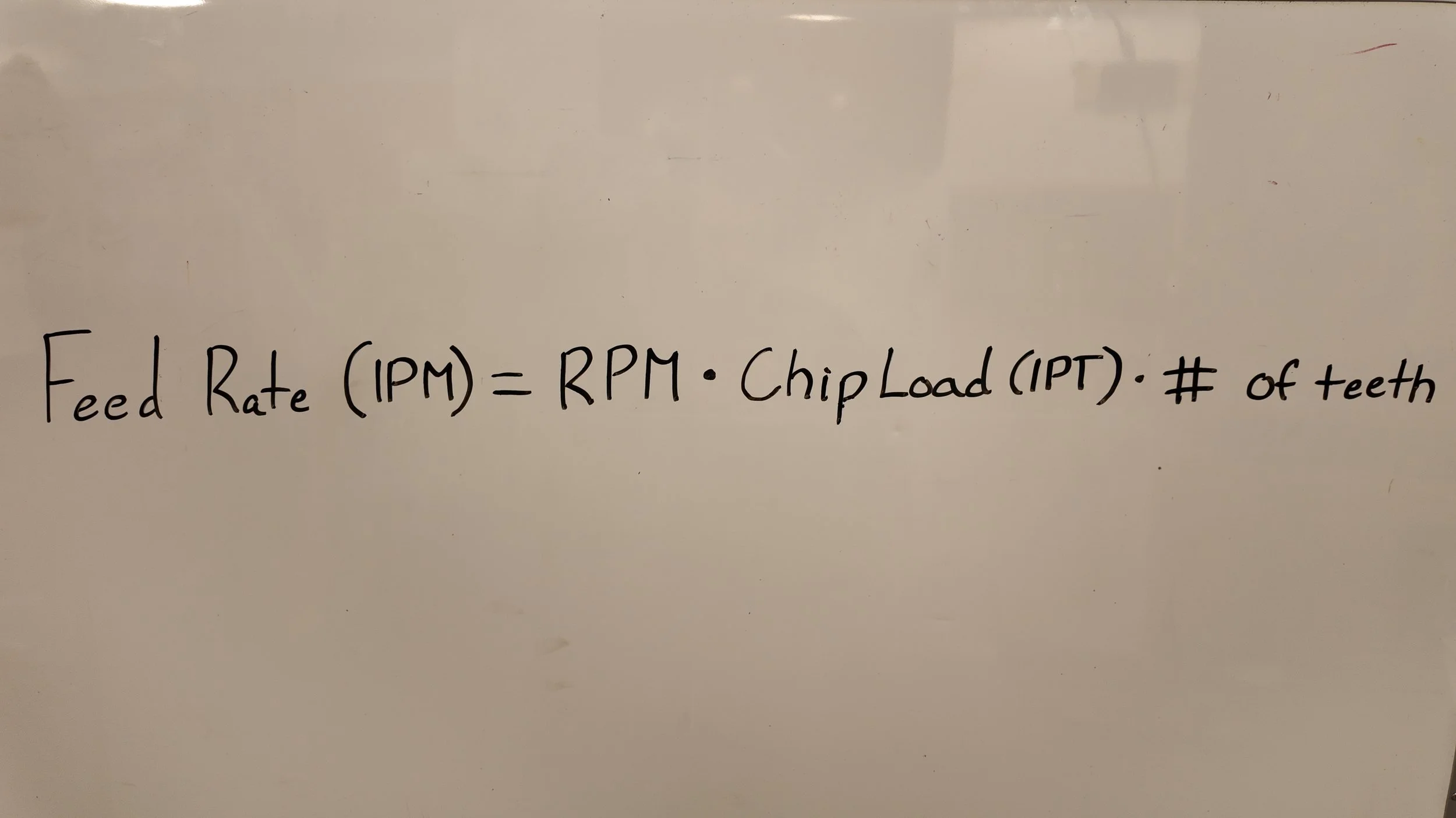
Feed Rate (IPM): RPM x Inches Per Tooth x Number of Teeth
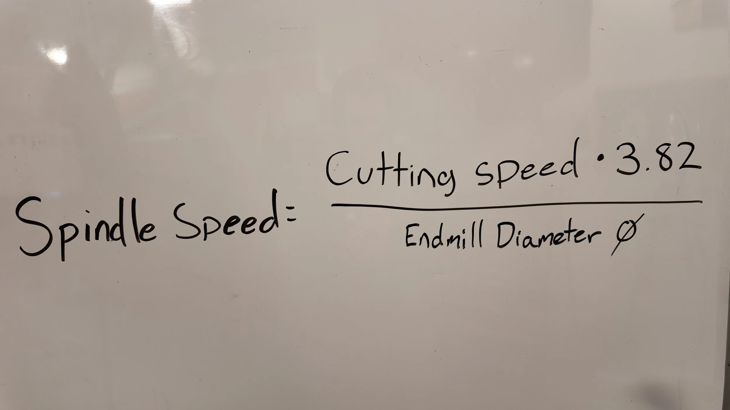
Now that we have the Cutting Speed (we’ll use 600ft/min as it’s easier on the machine) we can solve for Spindle Speed!
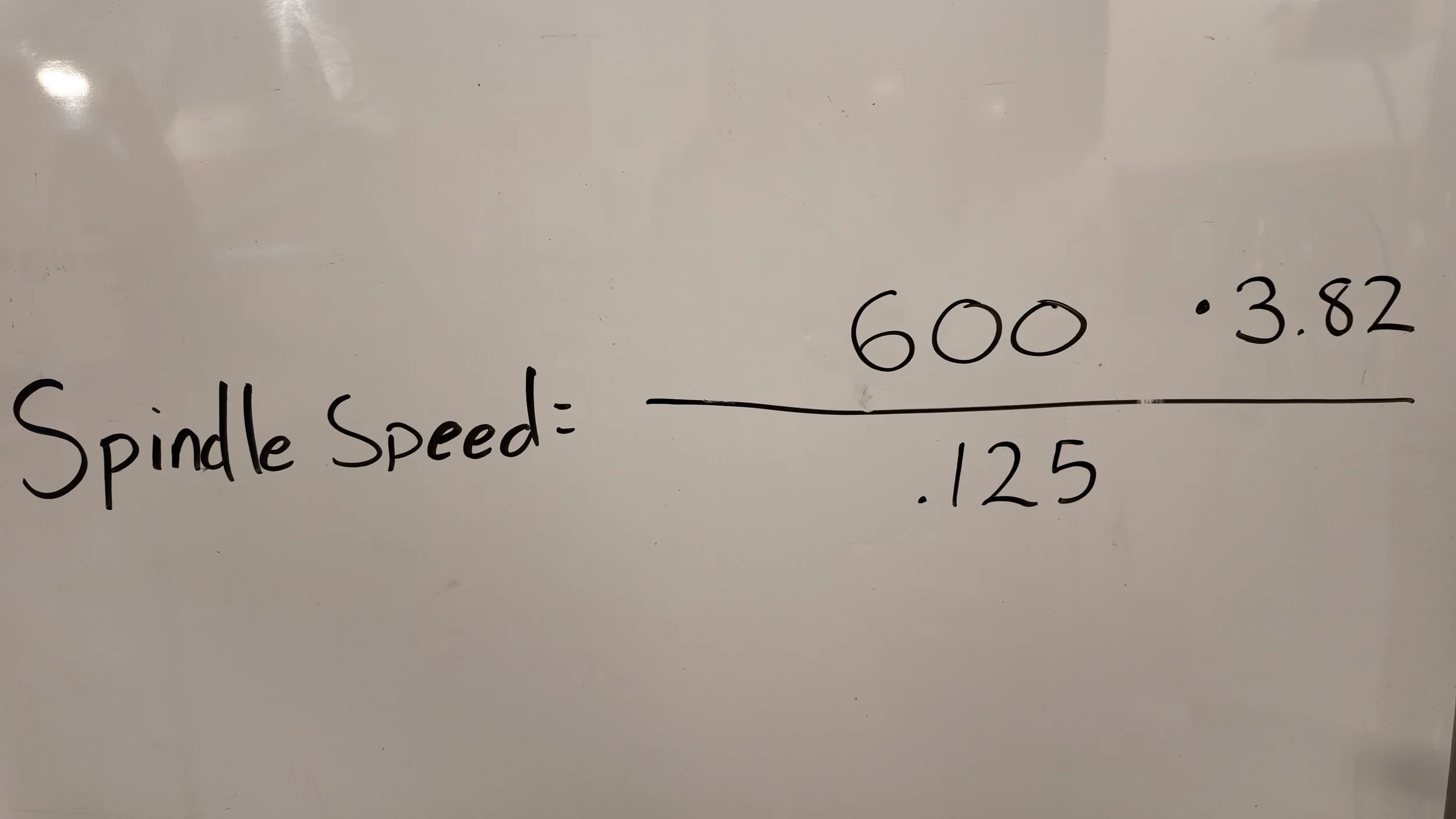
Spindle Speed = (Cutting Speed x 3.82) ÷ Endmill Diameter
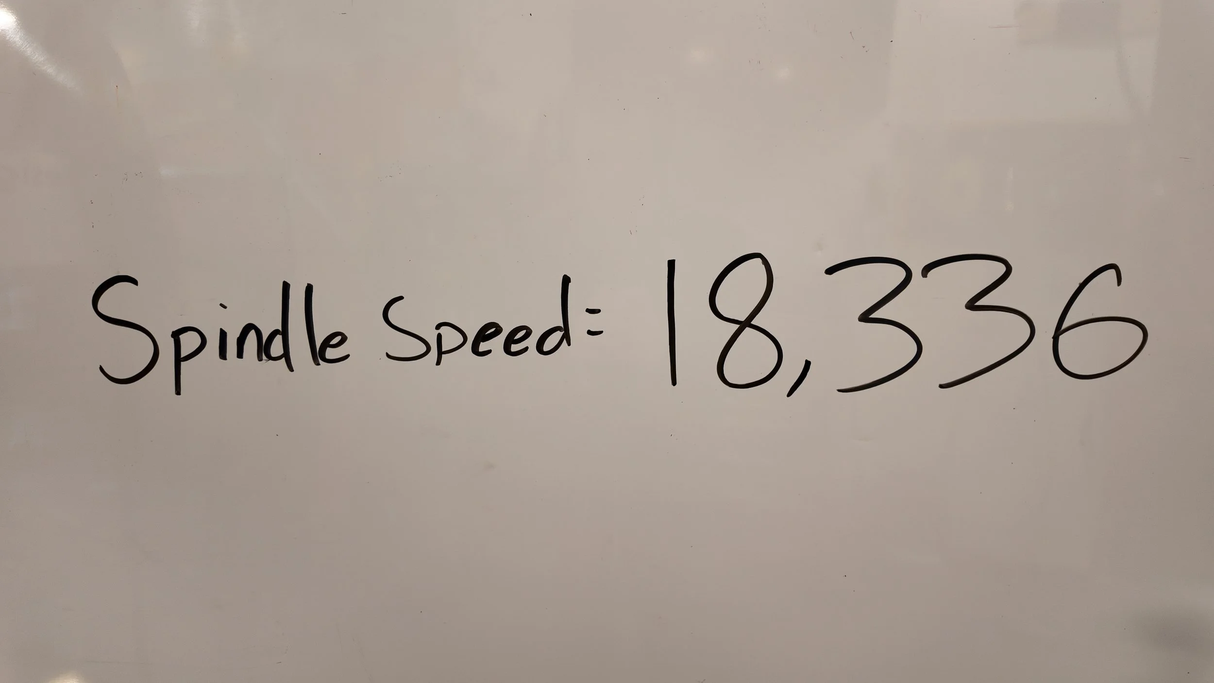
Solving gives us a Spindle Speed of 18,336 Revolutions Per Minute
Below is the equation drawn out for finding Spindle Speed which is how fast the endmill will spin in revolutions per minute.
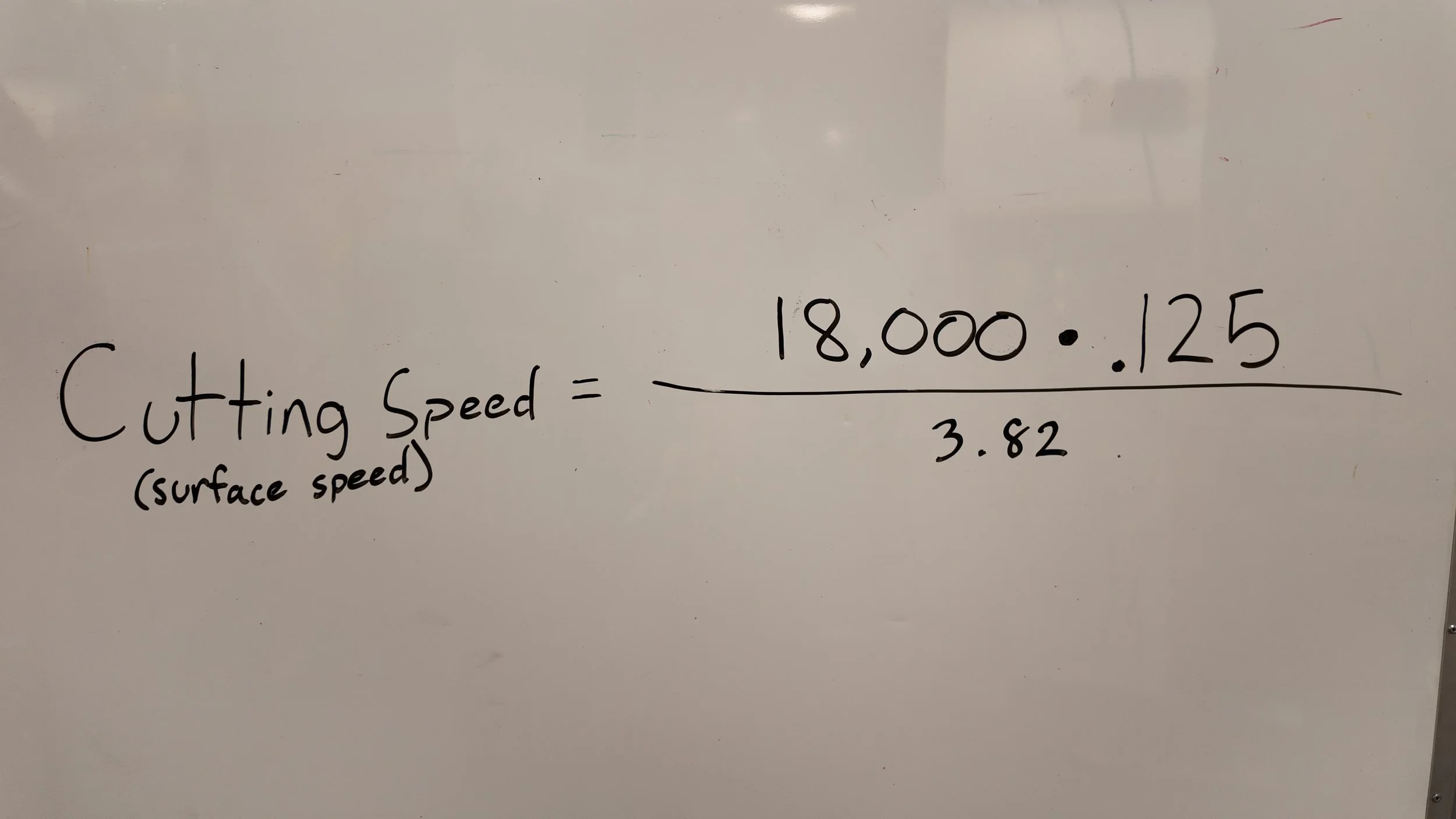
Unfortunately, our machine caps at 18,000 RPM, so lets recalculate our Cutting Speed using 18,000 as our Spindle Speed.
Cutting Speed (SFM) = (Spindle Speed x Endmill Diameter) ÷ 3.82
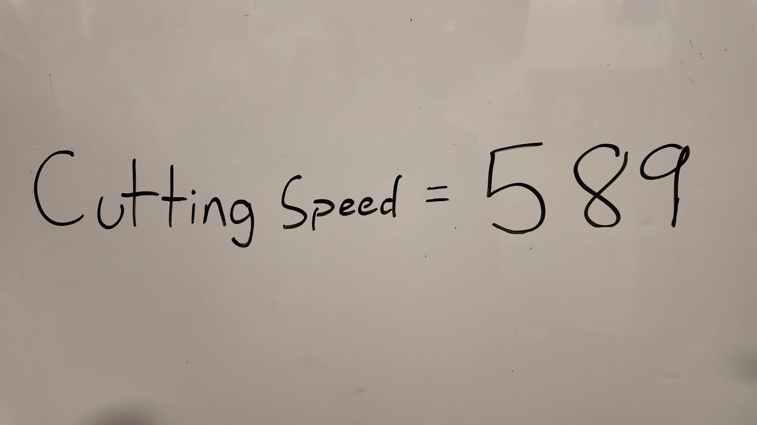
Solving gives us a Cutting Speed of 589 Surface Feet per Minute
Now that we know our Surface Speed and Spindle Speed, we need the Feed Rate - How much material to remove per minute.
We can solve for this with this equation!
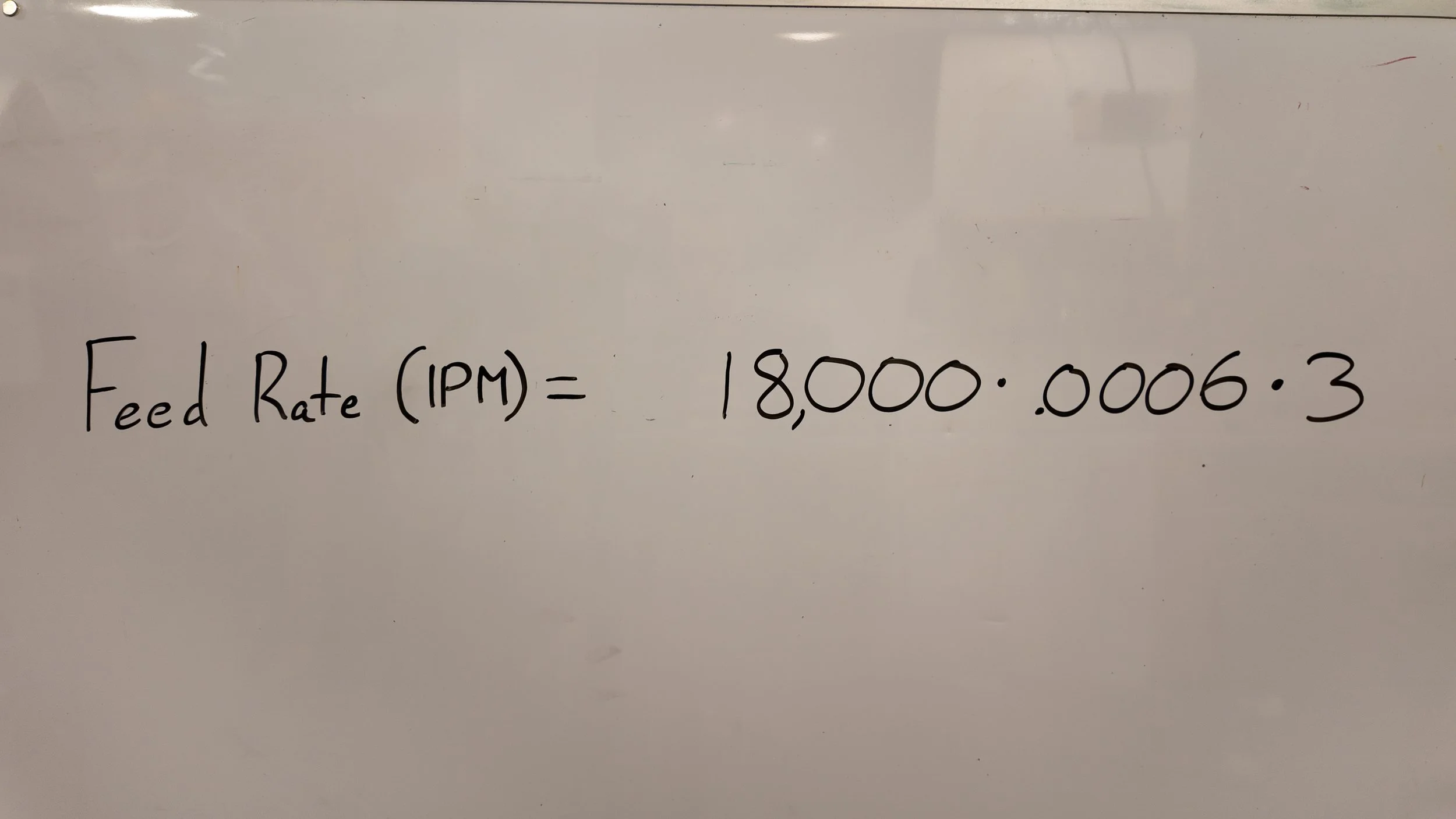
Feed Rate (IPM) = RPM x Inches Per Tooth x Number of Teeth
We know RPM because we solved for it, we know Inches per Tooth since it is on the Manufacturer sheet, and we know the Number of Teeth by looking at our endmill.
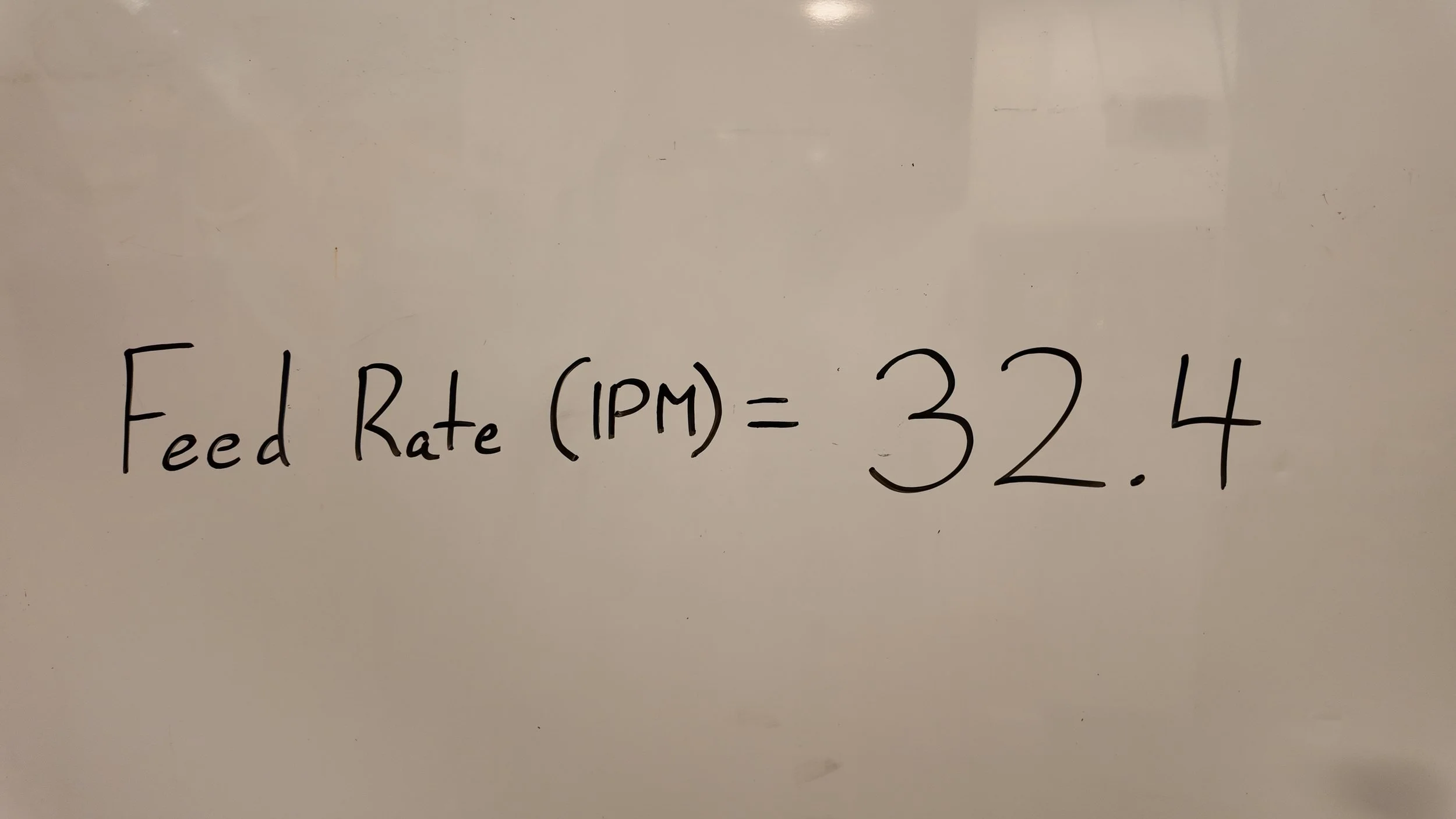
Solving the Equation gives us a new Feed Rate of 32.4 inches per minute
With these Calculated, we can move on to design and programming in Fusion 360.
Just a reminder, here was our calculated Speeds and Feeds:
Cutting Speed / Surface Speed: 589 Surface Feet Per Minute (SFM)
Spindle Speed: 18,000 Rotations Per Minute (RPM)
Feed Rate: 32.4 Inches Per Minute (IPM)
Feed Per Tooth: .0006 Inches Per Tooth (IPT)
I also used a 1/4” Endmill to cut out our parts and got the speeds and feeds using these same equations. Here are the final numbers.
Cutting Speed / Surface Speed: 800 SFM
Spindle Speed: 12223.1 RPM
Feed Rate: 48.8924 IPM
Feed Per Tooth: .002 IPT
FUSION 360
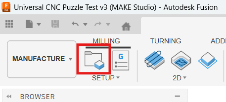
Once you’ve finished your design in Fusion, click on the Design Tab in the top left and switch to the Manufacture Tab.
Here is a link to the part being made: https://a360.co/3ZBFSIS
To go cover all the basics, I’ve created a puzzle piece that we can prepare for cutting out on the machine.
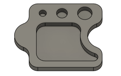
Notice all Corners are have a radius. Since all endmills are circular, it is impossible to cut a square corner.
Once in the Manufacture tab, Click on the Setup (Circled in red on image below)
Once Setup is selected, you should see a yellow Box appear around your model. This is the “Stock” or the size of the material we are physically cutting out.
Before we change the size of the Stock to match our physical Materials, Click on the bottom left most point on the stock box to change the origin location.
This is important because the machine cannot physically move in a negative X or Y direction. -Reference Below
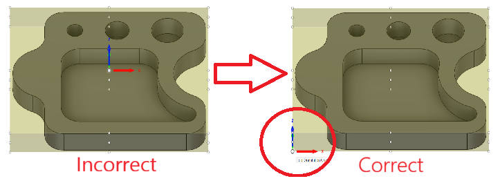
Notice how the XYZ axis changes to the Bottom Left of the Box
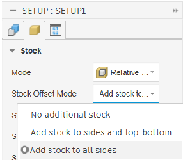
Clicking on the yellow box in the top left of Setup brings you to “Stock”
When choosing the Offset Mode, Choose “Add stock to all sides” (this allows us to be as precise as possible)
For this step we need to have the Physical Material that we want to cut out.
We then need the exact dimensions of our physical stock so we can enter it into Fusion.
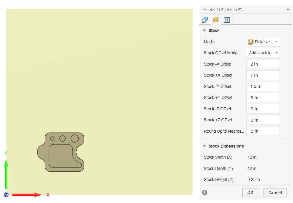
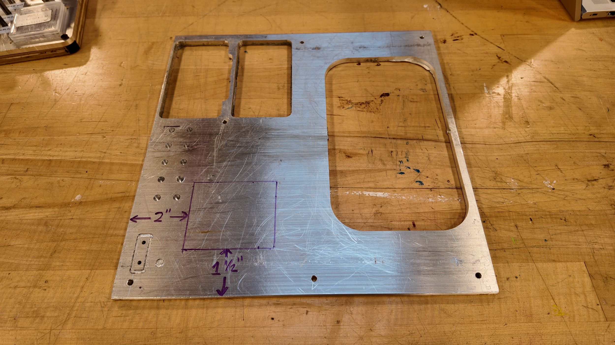
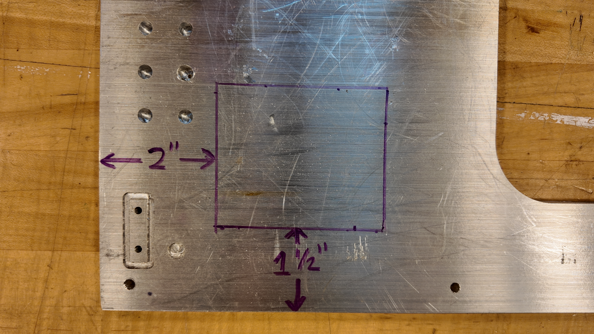
Above we can see how I add stock in the -x and -y to place my design in the unused portion of my physical aluminum stock. I then add stock in the +x and +y to bring my stock in fusion to 12”x12”, matching my physical aluminum sheet.
Once the Stock in Fusion matches your physical stock, select OK.
Note: When placing your design within your stock, give extra space for the tool to run along the outside of the design in order to cut out your design.
When cutting simple designs, you can cut out most things with 2D Pocket, 2D Adaptive, and 2D Contour.
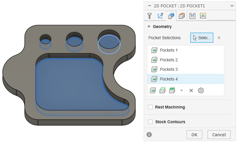
We will begin with a 2D Pocket to cut out all the shapes within the Puzzle Piece.
The first thing to do after selecting “2D Pocket” is selecting Geometry. While in the Geometry Tab, you can select the bottom of all pockets in your design.
Note: If you want to cut a hole the same diameter as your endmill, use Drill with “Chip Breaking” enabled instead.
Once the Pockets are selected, move to the “Tool” Tab and let’s add our endmill!
Here are the steps for adding your endmill to Fusion
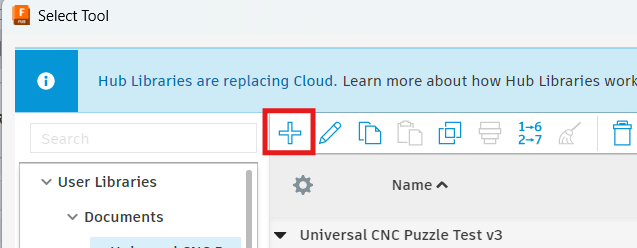
On the Tool Tab, click the “Select” button
On the Select Tool screen, select the “+” button
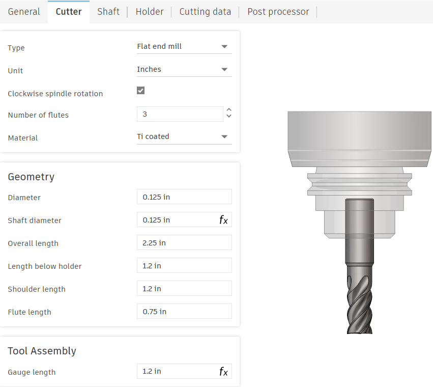
On the resulting screen, name the Endmill, fill out the dimensions and hit “OK”
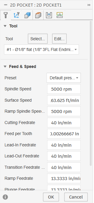
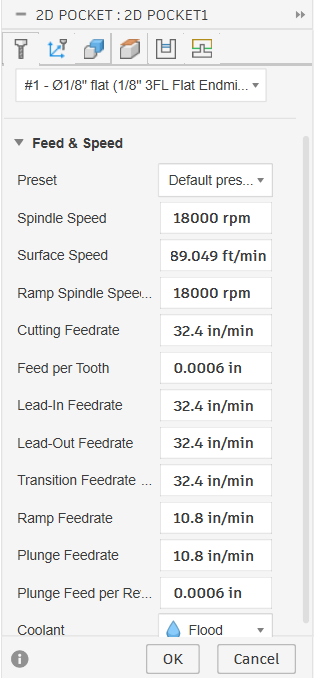
Now that we have our endmill in Fusion, let’s put in our Speeds and Feeds we figured out earlier.
Fusion automatically does the math as long as it has all the variables from the equations earlier.
For example, Once we have our tool selected (1/8” Flat Endmill) and we input our Spindle Speed as 18,000 RPM, Fusion will automatically calculate our Surface / Cutting Speed as 598.049 ft/min
What this means, is that as long as you have:
1) Spindle Speed OR Surface / Cutting Speed
AND
2) Feed per Tooth OR Feedrate
You have everything you need to get your speeds and feeds, AND Fusion will do the math for you.
The “Multi-Axis” tab is never used as our machine is only a 3-Axis machine
The “Heights” Tab is important when using large clamps or need increased clearance. In the heights tab, adding to the offset on the “Retract” Height will make the machine move physically higher when its moving between cuts.
The next important tab is the “Passes” Tab.
The Passes Tab includes instructions for how the machine will cut. The most important setting under Passes is “Stepover”
When choosing a stepover, use your Endmill Diameter x % tool engagement.
Standard engagement for roughing passes is 40%-60%, however, I have broken endmills at 40%, so instead, I am using 30% tool engagement.
1/8 x .3 = 0.0375” Stepover
Note: Increasing Stepover will decrease machining time significantly
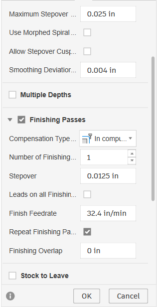
The next part of the Passes tabs is “Finishing Passes” a finishing pass will reduce the stepover on the last cut to provide a clean finish. If using Finishing Passes, checkmark “Repeat Finishing Pass” to get the best results.
Stock to Leave is important when you want to leave extra stock, OR cut deeper into the stock by using a negative number in stock to leave.
Smoothing and Feed Optimization are all-around useful and should always be turned on.
The final tab is Linking. Linking controls many settings for how the Machine moves outside of standard cuts.
The first subsection in the Linking tab is… linking.
Here the main things to note are Safe Distance and Maximum Stay-Down Distance. Safe Distance is the distance the tool will retract above the workpiece when moving to a new area. (I find it easier to change the retract height in the Heights tab but either options work)
Maximum Stay-Down Distance says: When travel distance is greater than the Maximum Stay-Down Distance, it will raise the endmill to the retraction height before moving. Note: Once the tool path is created, if there is a lot of yellow lines (traversal moves) in the toolpath, Increasing Stay-Down Distance can decrease machining time.
Leads and transitions is the next subsection. All the lead in and lead out does is make a half loop when entering and exiting the material to give a better finish. On outside cuts turn off Lead Out as it will move into the stock at the very end with full tool engagement.
The next section is RAMP and is very important.
Ramp type: Should always be Helix
Ramping Angle: Should always be 2°
Maximum Stepdown: no more than half the tool’s diameter.
Ramp Clearance Height: Only change if you want to change how quickly the endmill enters the material
Ramp Radial Clearance: Only set if you don’t want the tool to use the entire hole diameter when cutting with the helix
Helical Ramp Diameter: The diameter of the Helix going into your pocket. If toolpaths won’t generate on small pockets, decrease this
Minimum Ramp Diameter: Same as Helical Ramp Diameter, just the minimum diameter
The final section under linking is Positions.
The most useful among the three settings is Predrill Positions. If you have already removed stock on a previous operation, Selecting a predrill position will allow the endmill to drop straight into the pocket without worrying about entering the material slowly. Only use Predrill if you have cut to the bottom of your pocket on a previous operation.
Preferred Lead in allows you to choose where the machine will enter the material. Note: The lead happens at the very beginning and will most likely be done above the material due to safe distance heights. This means that often nothing changes based on lead in.
Exit Position allows you to choose where the machine will finish cutting.
Now that all settings are complete, select OK and a toolpath will generate.
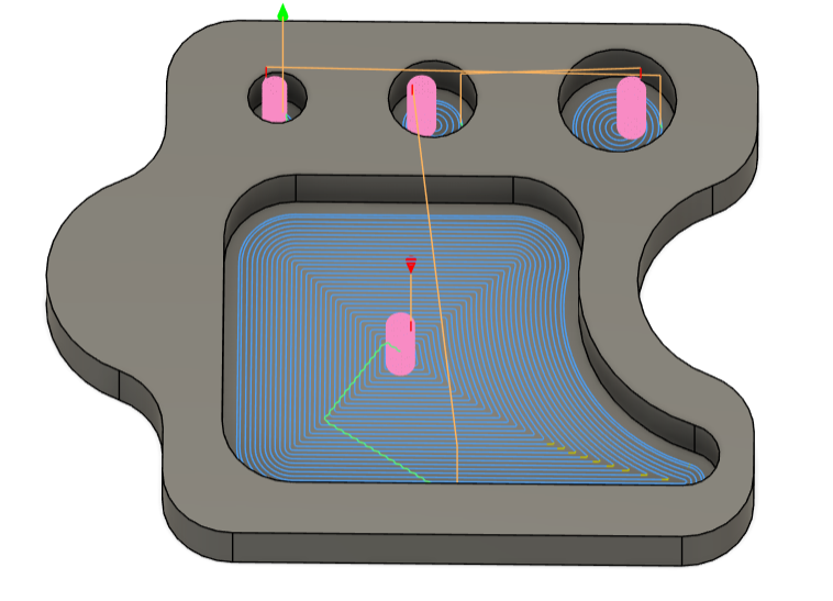
Once the toolpath is created, you will see these lines (seen in image)
Blue - Cutting toolpath
Pink - Helix
Green - Stepover
Yellow - Traversal
The space between cutting lines is small due to me using a small endmill with very little stepover. Cutting times can be greatly reduced using larger Endmills and/or greater stepover.
NOTE: Post operation me here… The endmill broke using the settings listed above for one reason. When the toolpath follows the contour of the pocket, in sharp corners (like the bottom right of the large pocket) there is more tool engagement. The increased tool engagement led to tool deflection and eventually, the Endmill breaking.
The Good News: This is easily fixed with 2D Adaptive, which shares most settings with 2D Pocket.
What’s different with 2D Adaptive: Instead of Stepover, we have “Optimal Load” (found in the passes tab). What this means is that, where 2D Pocket traces the outline of the shape with a set stepover for each pass, 2D Adaptive will create a toolpath that is constantly engaged with the material at the optimal load.
For 3/8” and 1/4” endmills: A great optimal load for Aluminum is .02
2D Pocket is typically more time efficient due to less traversal time, but 2D Adaptive is easier on the endmills.
Now that we’ve used either a 2D Pocket or 2D Adaptive to cut out the inside, let’s use a 2D Contour to cut out our design!
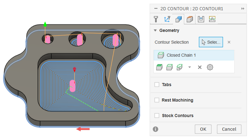
Selecting the outside contour of our design on it’s bottom, you will see a blue ring appear. (make sure you’re in the Geometry tab)
Make sure you have the same Tool and Speeds and Feeds from our 2D Pocket entered into the Tool tab.
An application for the Heights tab on Contours is that you can add an offset to the Top Height so that the machine will do a full pass in the air before cutting into the material allowing you to make sure you won’t hit any securing vices or screws
In the Passes tab, enable Smoothing and Feed Optimization.
When Contouring you can either use a Ramp or Multiple Depths. Multiple Depths plunges down a set stepdown before cutting each time, whereas Ramp will gradually and continually cut while moving down a set stepdown.
In general, I prefer Ramp, as it can be used on all materials, so that’s what we will be doing.
The Ramp settings for Contour are much smaller, only containing Ramping Angle, Maximum Ramp Stepdown, and Ramp Clearance Height.
Make sure the Ramp Stepdown is LESS than half your tool’s diameter.
The Final Piece is Tabs, Which are found in the Geometry tab. Turning on Tabs will leave small pieces of material holding the Design to the Stock which is VERY IMPORTANT if the Designed piece we are cutting out is not directly screwed down to the spoilboard. I recommend at least 2 Tabs for Aluminum, and at least 4 Tabs for Wood.
With these finished you can hit “OK”
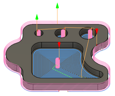
Note: The gap in the bottom of the outside cut is where the Tab will be.
Exporting
The final step in Fusion 360 is Exporting.
The Steps for Exporting are as follows:
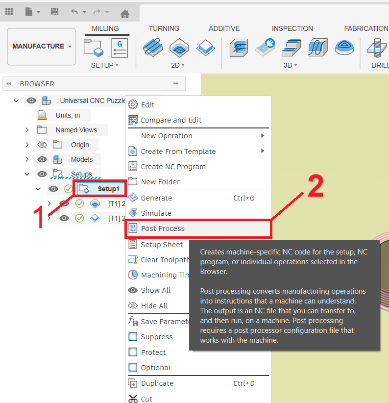
Right click on our existing Setup (under Part Browser)
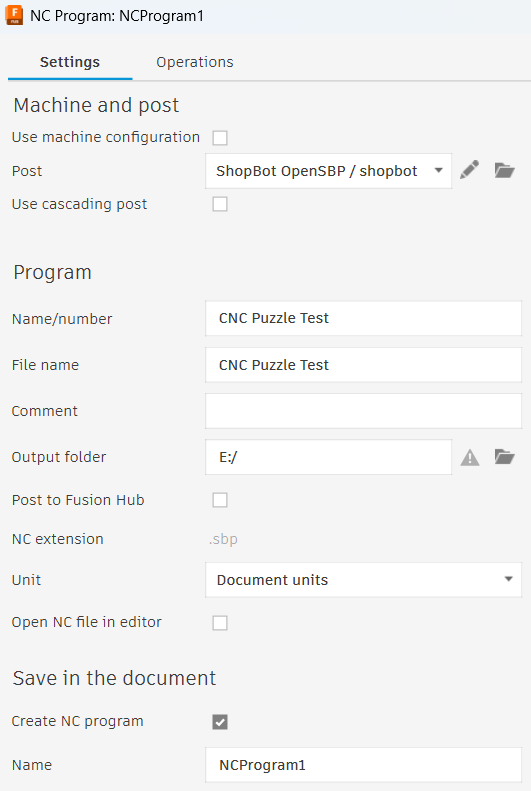
Click on Post Process
Next to Post, select “Shopbot OpenSBP” as your machine (or the machine that you are using)
Change the Program Name/Number
Select your Output Folder as a flash drive
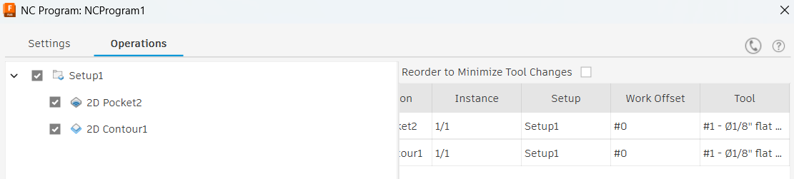
Check the Operations Tab to check all Pockets and Contours are selected (also verify the is correct tool here)
Click “Post”
Now eject your flashdrive and plug it into the computer connected to the Shopbot CNC.
The Shopbot Desktop Max
The first thing to do when setting up the machine is turning it on.
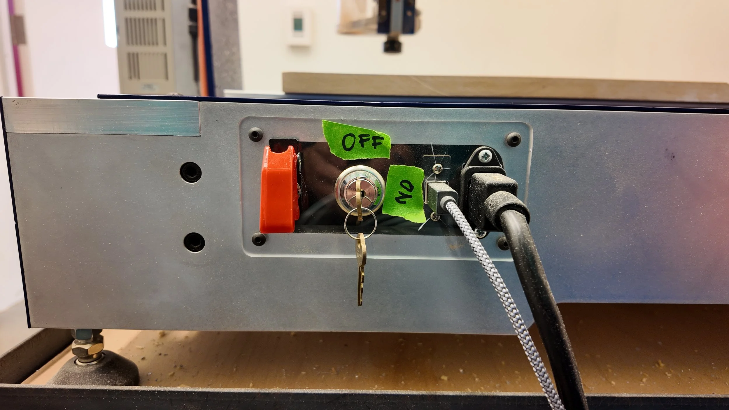
On the right hand side of the machine is this Key Panel.
The Red Lever is the Power Switch. Lifting the red cover and flicking up the switch underneath will power on the machine.
To the right of the Power Switch is the Spindle Key. When the Spindle Key is off, the machine cannot spin the Endmill. This is an important safety mechanism and the Spindle Key should be off during Tool Changes and Zeroing the Z-Axis.
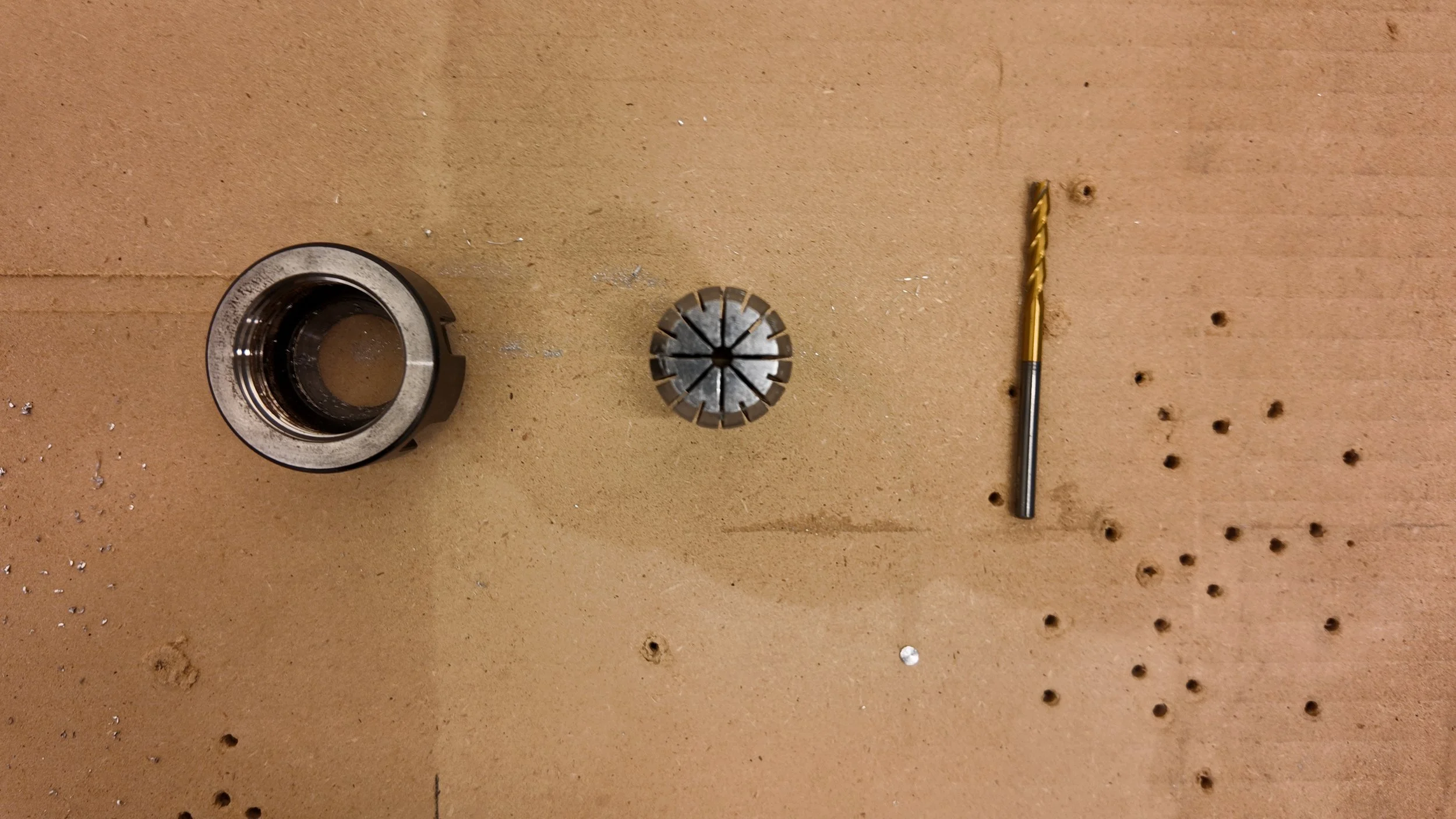
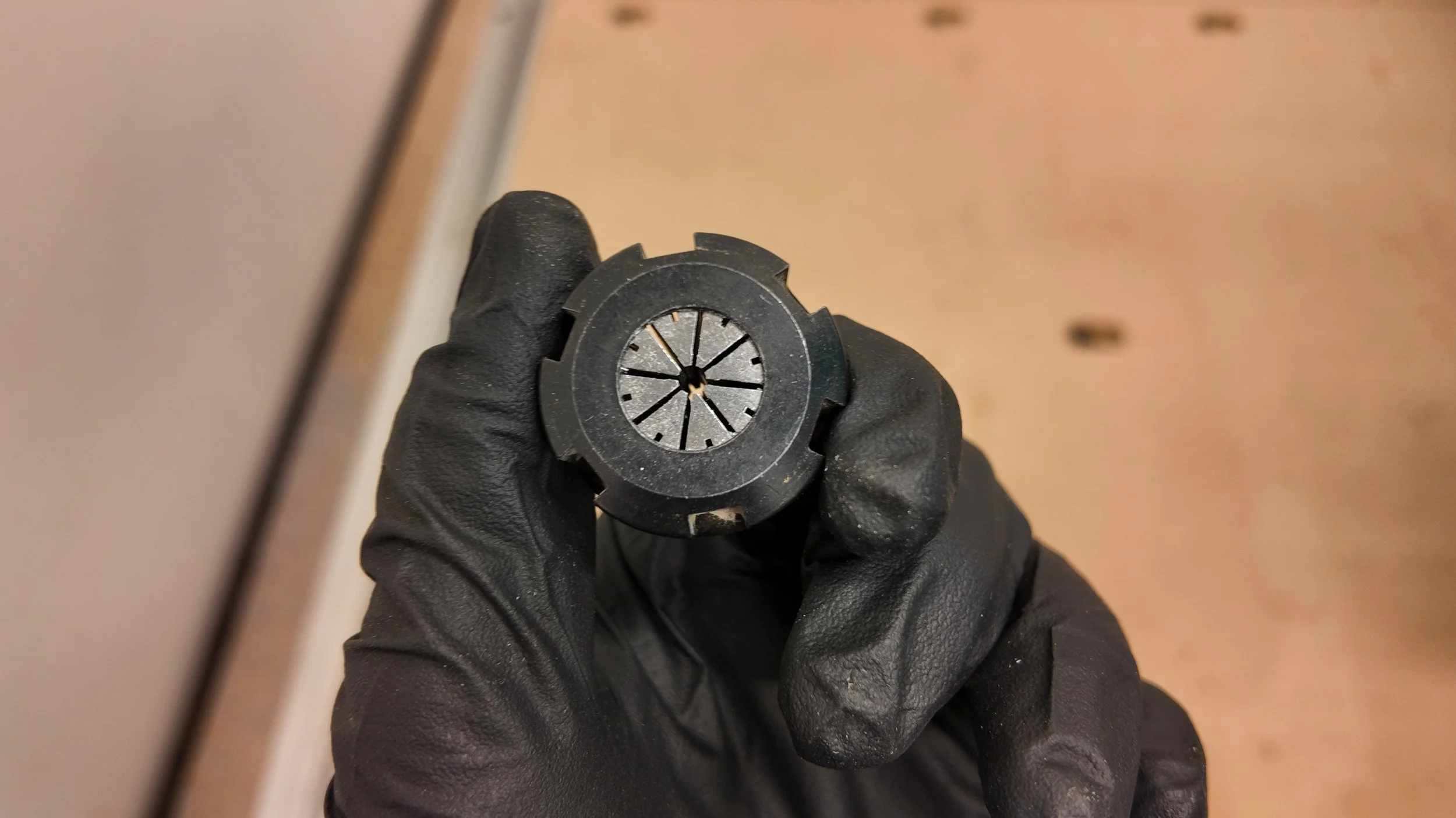
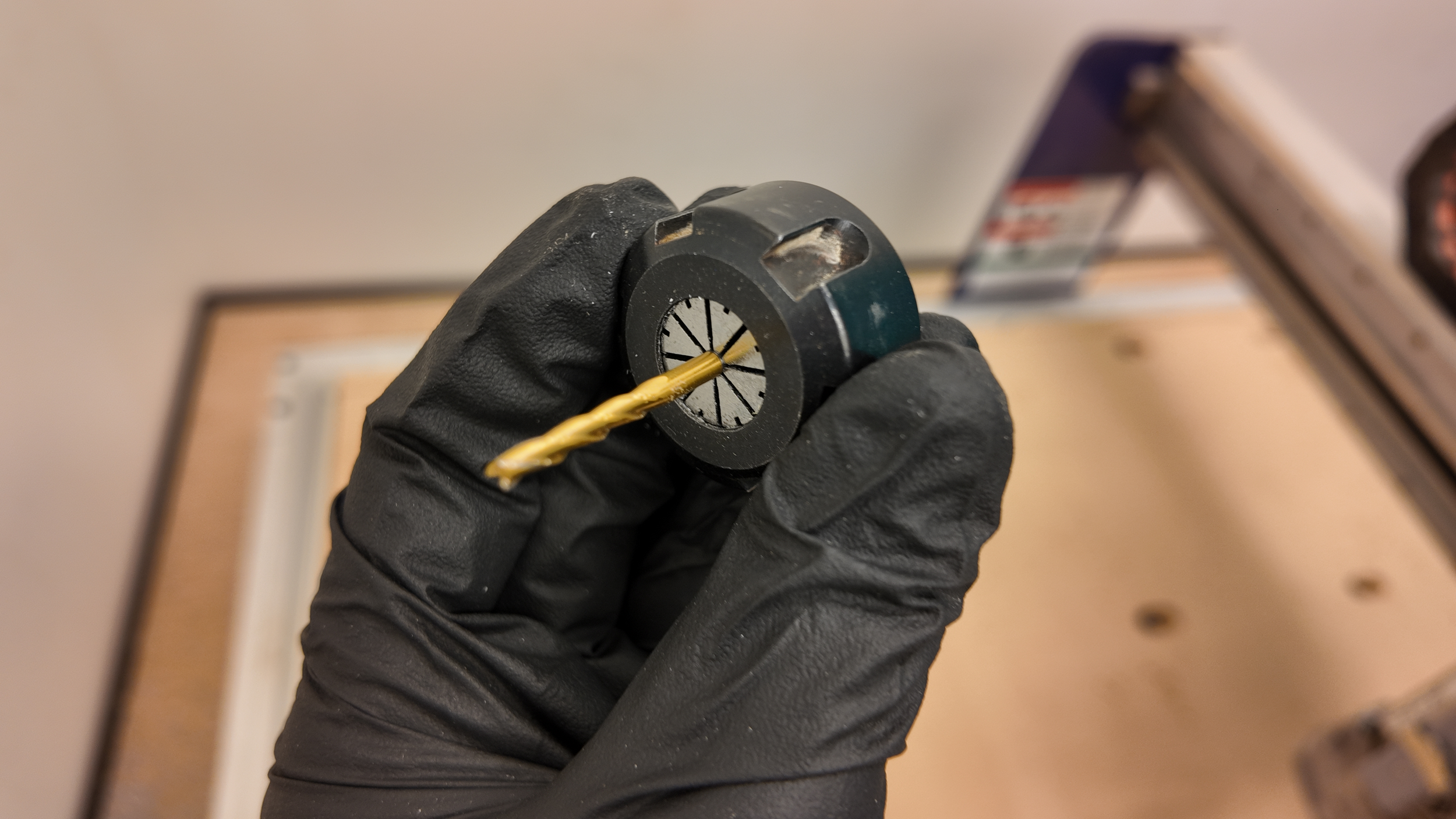
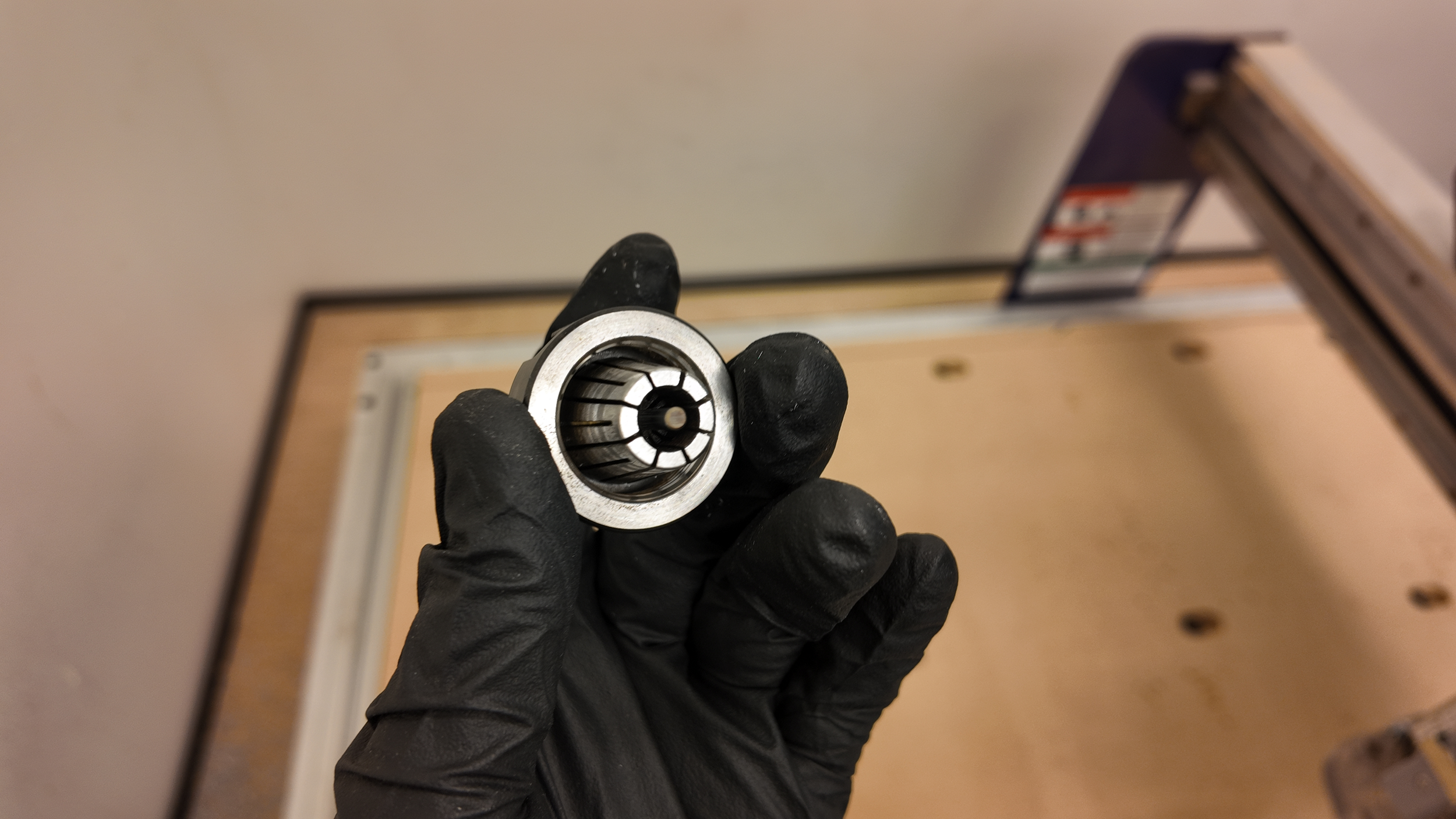
When doing a Tool Change, You must know that the Tool holder is comprised of 3 parts. The Nut, Collet, and Endmill.
The steps for a tool change are:
Turn off the Spindle Key
Use the two wrenches to loosen and remove any endmills currently in the holder
If collet size is correct, insert new endmill and tighten in holder
If collet size is incorrect, finish unscrewing the Nut
Replace the collet in the nut with the correct size collet
Screw back on the nut and tighten the endmill in the new collet
(Reference images Below)
With our Endmill fastened securely in the machine, we can now warm up the spindle while we finish preparing our workpiece.
In order to warm up the spindle, we must understand “ShopBot 3”.
ShopBot 3 is the Software that the ShopBot Desktop Max uses to read code. ShopBot 3 has 2 interfaces. “Full” and “Easy”. Warming up the spindle is the only thing done in the Full version of ShopBot 3. Everything else is done in Easy mode.
After Booting up ShopBot 3, it will most likely be in Easy mode. To switch to Full, click on the blue “?” Box and select “Switch to Full”
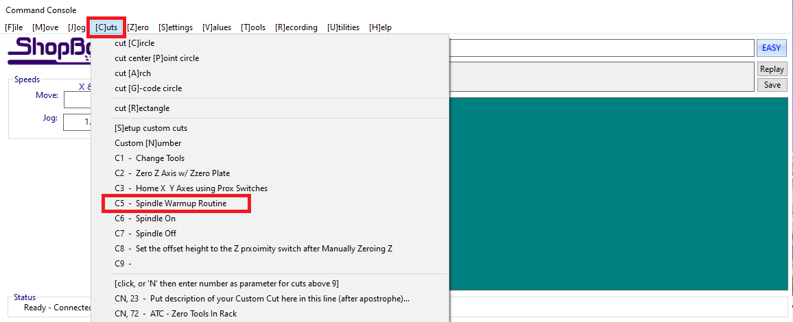
When in ShopBot Full, Click the “[C]uts” tab and select “C5 - Spindle Warmup Routine”. (alternatively you can just type C5)
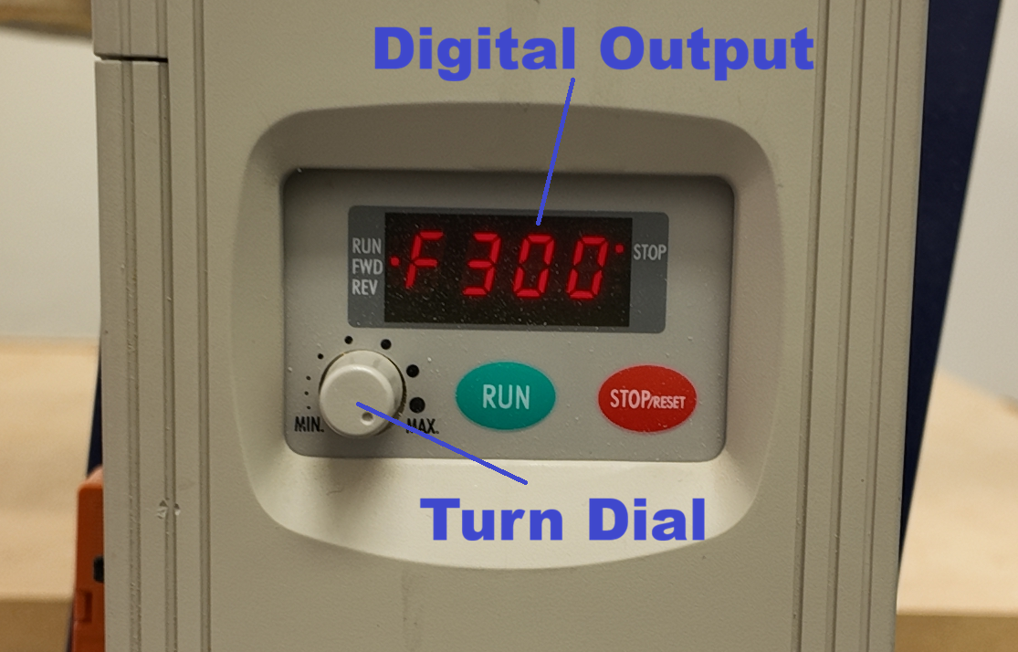
After selecting Spindle Warmup, a prompt will appear asking you to set the Hz to 150. To do this, Turn on the Spindle Key. On the Display mounted to the machine, it will display a number from 0-300. Turn the connected Dial until the display reads 150Hz.
Every 3 minutes turn up the Spindle Speed by 50Hz and after 9 minutes the spindle is warmed up
The Hz number is Directly tied to Spindle Speed. In fact, the Hz number is your Spindle Speed ÷ 60
For example, our Spindle Speed is 18,000RPM / 60 = 300Hz. If you set the number on the display to 300Hz, it will spin the spindle at 18,000 RPM.
While the Spindle is warming up, we can secure our Stock material to the Wasteboard and prepare it for being cut.
To prepare your stock, Drill screw holes with a safe clearance for anywhere the tool may be close to contacting the screws. Alternatively, if you don’t use screws, you can use Clamps, but their extra Height requires a larger retract height in Fusion to be safe.
Fasten down your Stock in the bottom left of the spoilboard with screws and/or clamps. Make sure not to tighten too much or it will tear out the MDF spoilboard and the screws will lose their grip.
Once the Spindle finishes warming up, we can start Zeroing our Axis. To begin, click the “Easy” button in the top right of ShopBot 3 to change ShopBot back to Easy mode.
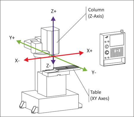
The X and Y Axis are flat along the bed while the Z Axis controls the verticality of the Endmill
To “Zero” an Axis means telling the machine the absolute limit of how far it can travel in one direction for each Axis. We Zero our Axis in the bottom left of the machine.
Luckily ShopBot does most of the work for us.
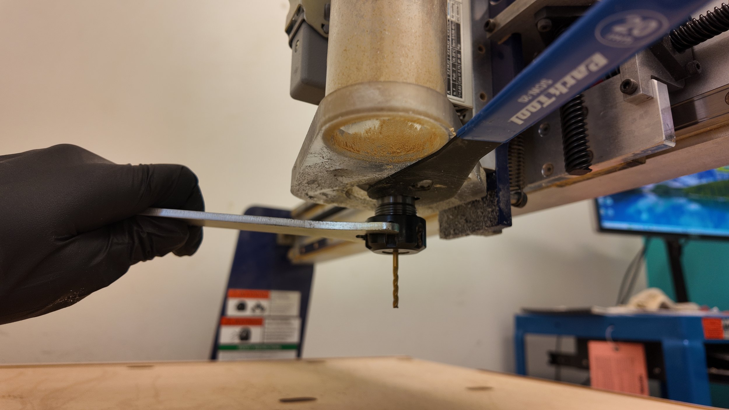
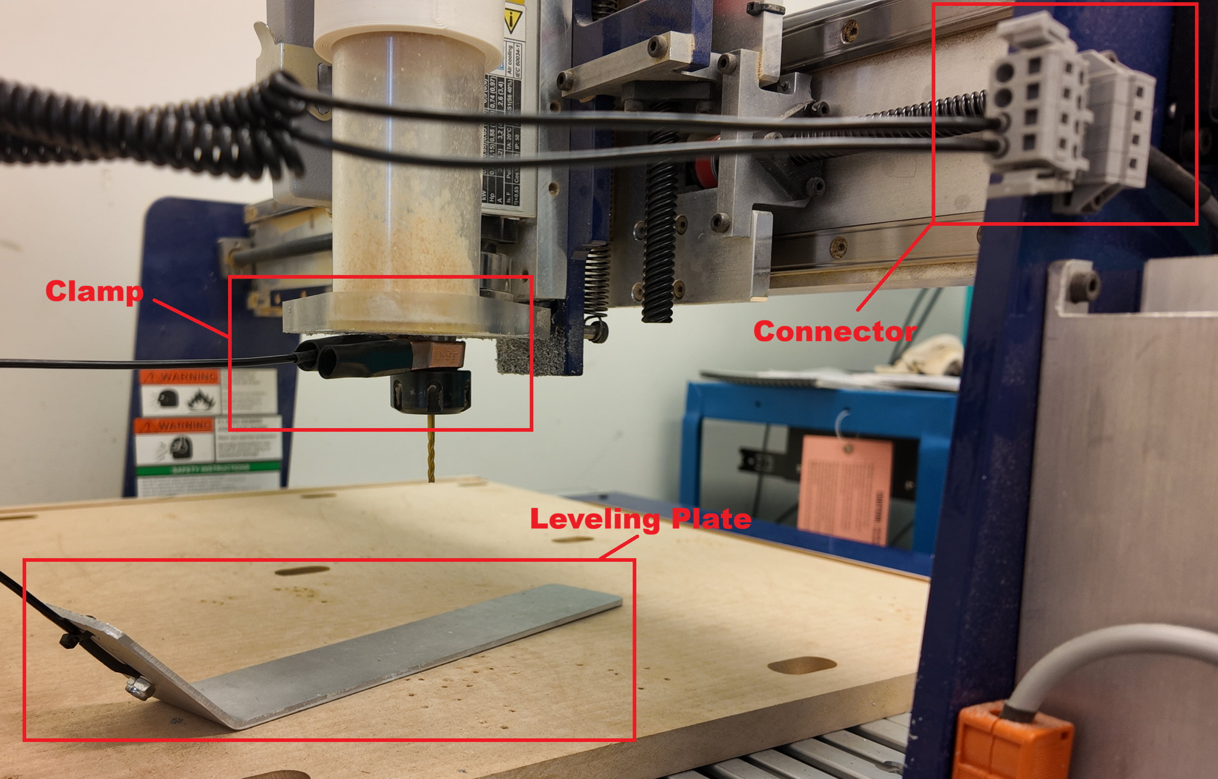
To Zero the Z-Axis, Turn off the Spindle Key, Place the Connector in its port, place the Clamp on the endmill or the metal part above the Nut, and place the Plate underneath the Endmill. (Reference image to the Right)
To make sure everything is set up correctly, touch the Leveling plate to the Endmill and watch ShopBot to see if Input 1 lights up. If it does, you’ve done it correctly.
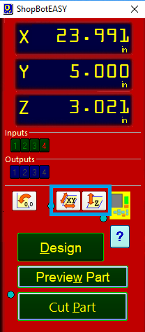
Once ready, click the Zero Z-Axis Button (The one circled in blue on the right) in Shopbot.
A prompt will appear asking you to make sure the Leveling Plate is right beneath the Endmill, once it is, hit “OK” and the machine will lower the endmill until it touches the plate beneath it.
Once the Z-Axis is zeroed, it will raise half an inch from the bottom of the board which is not enough clearance to avoid hitting our Stock.
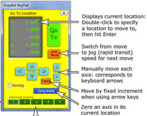
To fix this, click on the yellow miniature keypad on ShopBot Easy and wait for the “ShopBot KeyPad” to appear.
By either typing a new value in the Z Location or clicking the top arrow on the furthest right set of arrows, you can easily raise the Endmill up.
Note: If your raise the Z level too high it will jutter. If this happens you will need to re-zero the Z axis.
With the Endmill out of the way of our Stock, we can Zero the X/Y Axis.
After Closing out of the Keypad, press the Zero-X/Y Axis button to the left of the Z-Axis Button
Once the Zero X/Y button has been pressed it will immediately move to the left as far as possible, followed by moving down as far a possible to the bottom left corner. Once finished a prompt will appear on the computer signaling that it is done.
Final Pre-Cut Steps
Now that our X, Y, and Z Axis are Zeroed, our Stock is securely screwed into place, our Spindle is warmed up with the right tool in it, and we have our code exported on a flashdrive, We can almost begin cutting!
The last things are Your Personal Protection, and Preparing the Environment.
Eye Protection is essential, along with Hearing Protection. I also recommend a ventilation mask to filter all the dust created while milling. When cutting Aluminum, wearing a tight fit dense material jacket can protect your arms from aluminum chips. HOWEVER: Do not have pullstrings or a hood exposed as they can be pulled into the machine. If you don’t have a jacket, an apron is a great alternative.Finally, If you want gloves, don’t use anything more heavy duty than nitril / latex gloves.
Inside the CNC room there should be a Vacuum, Coolant Line and WD-40. When cutting Aluminum, Lubrication (WD-40) is required to keep the Endmill cool and assist in cutting.
The Coolant Line is capable of putting lubricant on the endmill, but is mostly used as an air assist by blowing the cut chips out of the pocket. Turn it on by turning the blue knob on top of the coolant line box. (Must be connected to the compressed air line or air compressor to work)
Turn on the overhead Vacuum and click “Cut Part” Select your file from the file directory and it will ask you to set the Hz. (The computer will say what value to turn it to) Turn the dial on the machine until the Hz on the digital screen matches.
After hitting OK, it will begin Cutting out your Part. While it is cutting listen for Rattling, Shaking, Vibrating, etc… If any of these get too strong, stop the cut and reduce the stepover.
Vibrating can also occur if the Stock is not secured well to the table.
The final thing I want to talk about before machining is what the tool should sound like while cutting there are two common sounds heard when something is wrong. Chattering and Scream / Squealing are caused by opposite problems.
Chattering: Caused by having too high of a chip load on the endmill. Can be fixed by slowly turning up the RPM (Hz) on the ShopBot. Chattering will also leave a rough surface finish on the sides.
Squealing: Caused by having to low of a chip load. Fixed by lowering the RPM (Hz) on the ShopBot.
This works because as the rotations per minute increases with the same cutting speed, the chip per tooth will decrease (and vise versa)
Here is a video of our machine cutting Aluminum.
I stopped the machine from finishing the outside cut in order to reduce the stepdown before running the outside cut again.
When Something Goes Wrong
Things going wrong is part of learning. That being said, you should always know what to do. While the machine is cutting, the mouse cursor is locked on top of the “STOP” button. Clicking the mouse or pressing the Spacebar at any time will immediately stop the machine. After it is stopped you can choose to “quit”, “resume” or “close and exit”. Unless you are resuming, press QUIT, as close and exit will close the ShopBot application which means we have to re-zero all axis.
Once Quit is hit, you can use the ShopBot Keypad to move the machine away from your stock and do any maintenance you need. If you need to change a setting in fusion, do it, and when exporting, (under operations) deselect any toolpaths that have already been completed.
Once exported, you can run the new file.
Wood
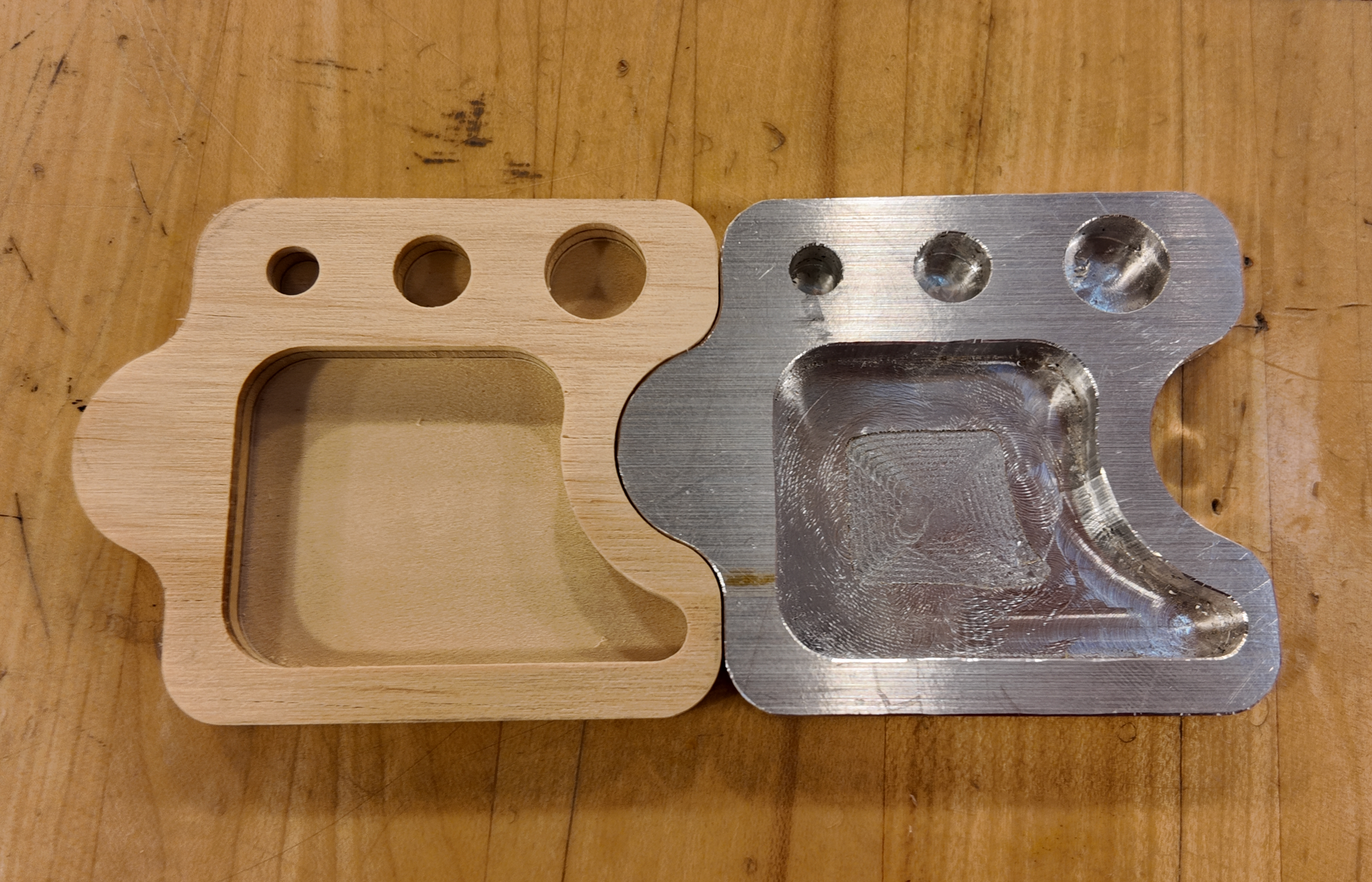
After cutting out the Aluminum, I also cut our puzzle piece out of wood.
With wood, the machine can cut with a higher feed per tooth / optimal load.
Wood is often warped, so it is important to screw the board down near where the design will be cut out to avoid air pockets underneath.
Here is a video of Wood being cut out with the same settings as Aluminum.
Post Process
Now that we have our Puzzle Pieces Cut out, let’s talk about Post Processing (Finishing) our parts.
In order to remove the tabs holding our part to the stock, we will secure our stock in a swivel vise before using an oscillating tool with a cutting blade attached. Alternatively a hacksaw can easily cut off the tabs.
Make sure both the Stock and Part are clamped in the swivel vise before cutting to avoid strong chatter. Any extra material still left can be grinded off on a belt sander.
With our part removed from the Stock, the only things left is presentation:
Freshly cut aluminum is covered in sharp edges. Using a handheld deburring tool, cut a small chamfer along all corners.
Wood can have fuzz left on freshly cut edges (typically because of a small feedrate) These can easily be removed with sandpaper.
Final Thoughts
With that, we have our finished product!
CNC Machining is a very involved trade where the hardest part is learning how to begin.
This Blog has gone through the topics of Endmills, Types of Milling, Speeds & Feeds, Fusion Manufacturing, Using a ShopBot Desktop Max, Cutting Parts, and Post Processing.
These are not small topics so I hope this blog had done a good job of familiarizing you with them.
The CNC truly has many capabilities, so… Here’s to you for reading through it!
Stay Safe, and make great things!
-Jonathan Siddoway