
How to CNC 3D objects
Hello Everyone!
This is going to be a short follow-up to the “CNC Machining Common Materials” Blog centered on 3D designs.
How are 3D designs different from what we were making before?
When making our puzzle pieces, we were using a technique called 2.5D or two and a half dimensions. What this means is that we were going down to a set height before cutting out a flat shape (Hole or pocket).
With true 3D designs, the elevation changes constantly which leads to new problems to deal with.
Here is a link to the fusion design: HERE
Let’s get into it.
Choosing a Design
When choosing a design, it is important to note that a “3-Axis Machine” like the one we have here at JUMP cannot cut sideways into the material, meaning that our designs can only have a raised surface.
To explain this:
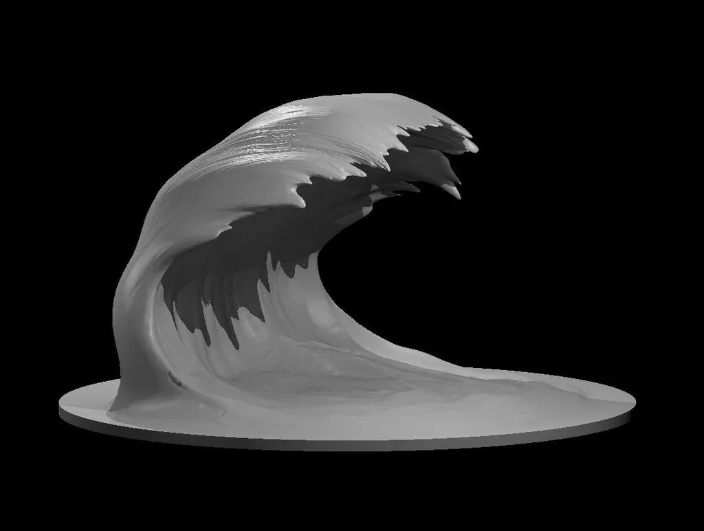
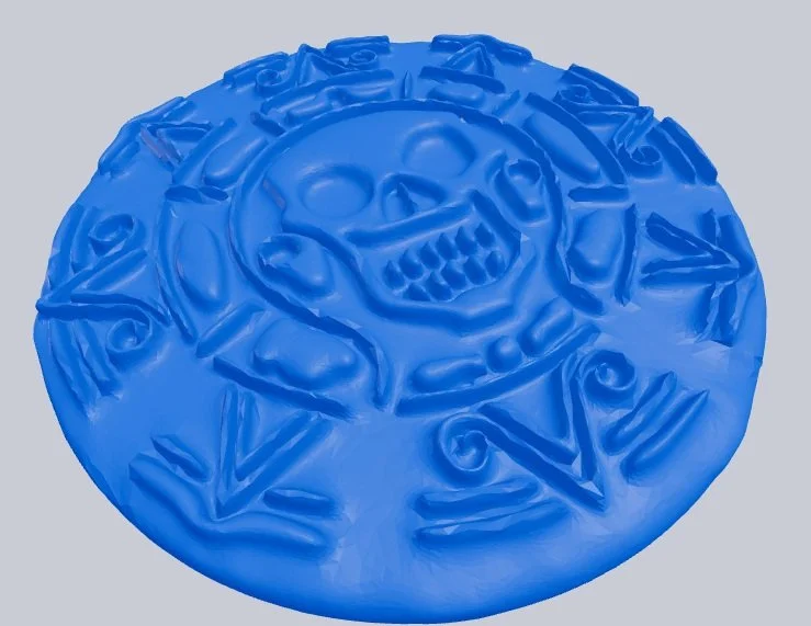
Here on the right we have two objects: A wave, and a coin.
The wave cannot be cut on the CNC machine because the tool cannot get underneath the crest of the wave to hollow out the middle.
The coin can be cut out since it does not have any overhangs.
One thing about the coin is that, depending on how small it is, it may be hard for an endmill to fit in-between the intricate markings. The bigger the design, the more precise the CNC can be.
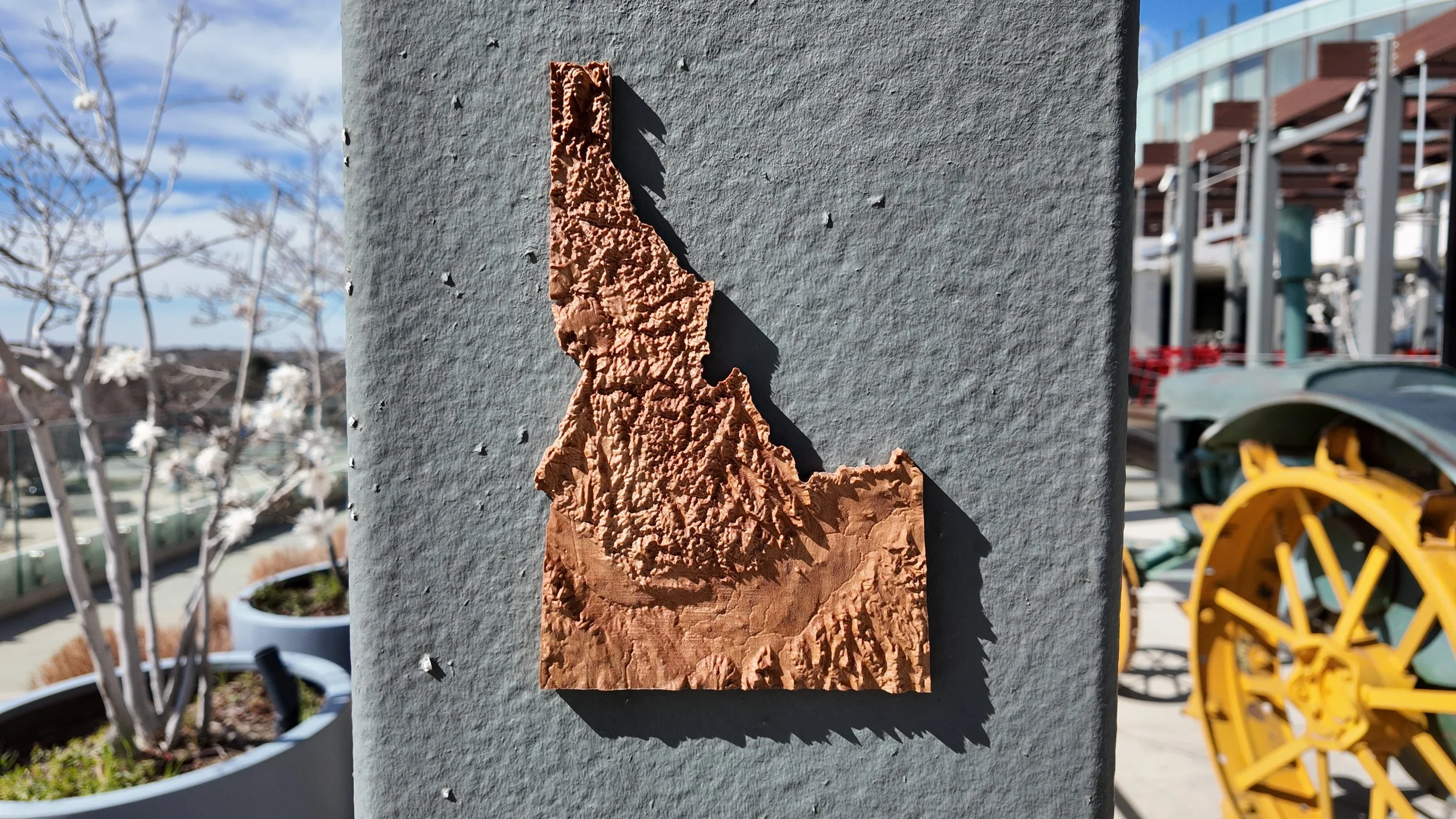
With JUMP being based in Boise Idaho, I wanted to make a 3D Topographical Map of Idaho. After searching online, I was able to find a creator by the name of Anson Liu on Printables. Who makes Topographical Maps of all the states.
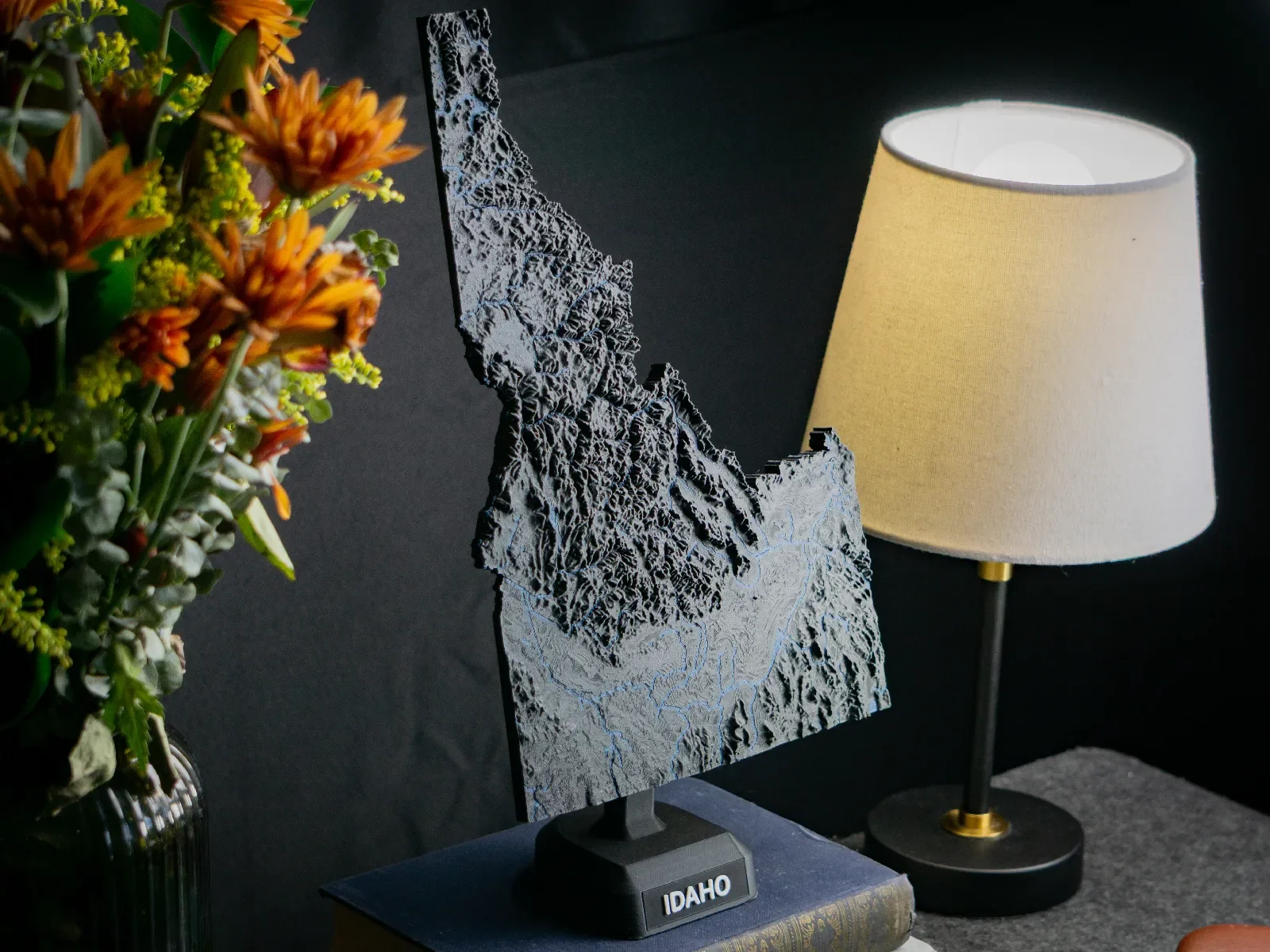
With the model of Idaho, I wanted to exaggerate the mountains and rivers by stretching the model in the Z-axis. To do this, I used Meshmixer since Fusion couldn’t edit the model while it was a mesh.
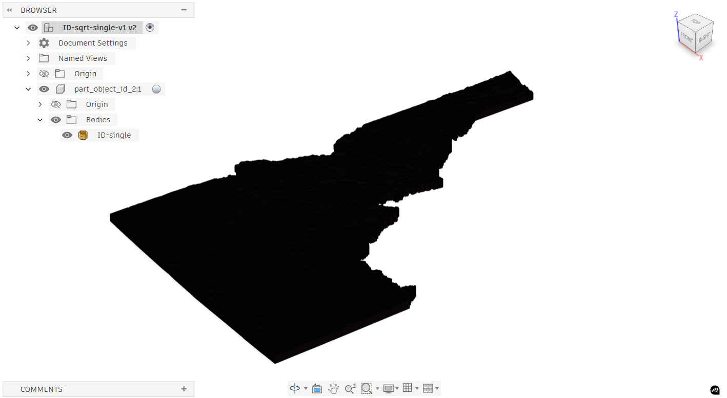
After uploading the stretched map to Fusion, I immediately realized it looks like a silhouette. This is because the Idaho design is so detailed that each line is close enough to each other that it just looks entirely black.
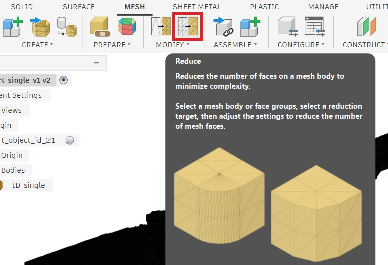
We need to simplify the design because with all the extra detail, rendering and design is very demanding on computers. We do this through “Reduce” under the “Mesh” tab.
Since the file was in a 3mf format and not a 3D object format (OBJ or STL), it imported into Fusion 360 as a “Mesh” instead of a “Body”. Meshes are much more common in animation and some forms of modeling, but for us, we want to convert our Mesh into a Body.
Once our mesh is reduced and simplified, we can convert it from a mesh into a part. Using the “Modify” dropdown (right beneath reduce) you will find “Convert Mesh”. In general the “Prismatic” option is better than “Faceted” as it simplifies the design even more, however, it can drastically increase the time to calculate.
Note: Even after reducing the part, and converting using Faceted to speed up the process, it still took nearly 20 minutes to finish turning the mesh into an object
One thing of note is that many of the decisions going forward are made with rendering time in mind.
For reference,
<5k faces: Small amount of time or instantaneous to render
5-20k faces: Moderate amount of time to render
>50k faces: Very slow and can fail
Our Idaho model (after simplification) is made of 216596 faces which is significantly more than 50,000. Every time I would make an adjustment to toolpaths, the design, or try and simulate, it would commonly take 30 minutes to finish computing.
With that said, let’s get into model preparation!
Model Preparation
To understand the prep, we need to talk about what we’re trying to do.
The general idea is to remove as much material with a large endmill as possible, then switch to a smaller endmill to cut the design
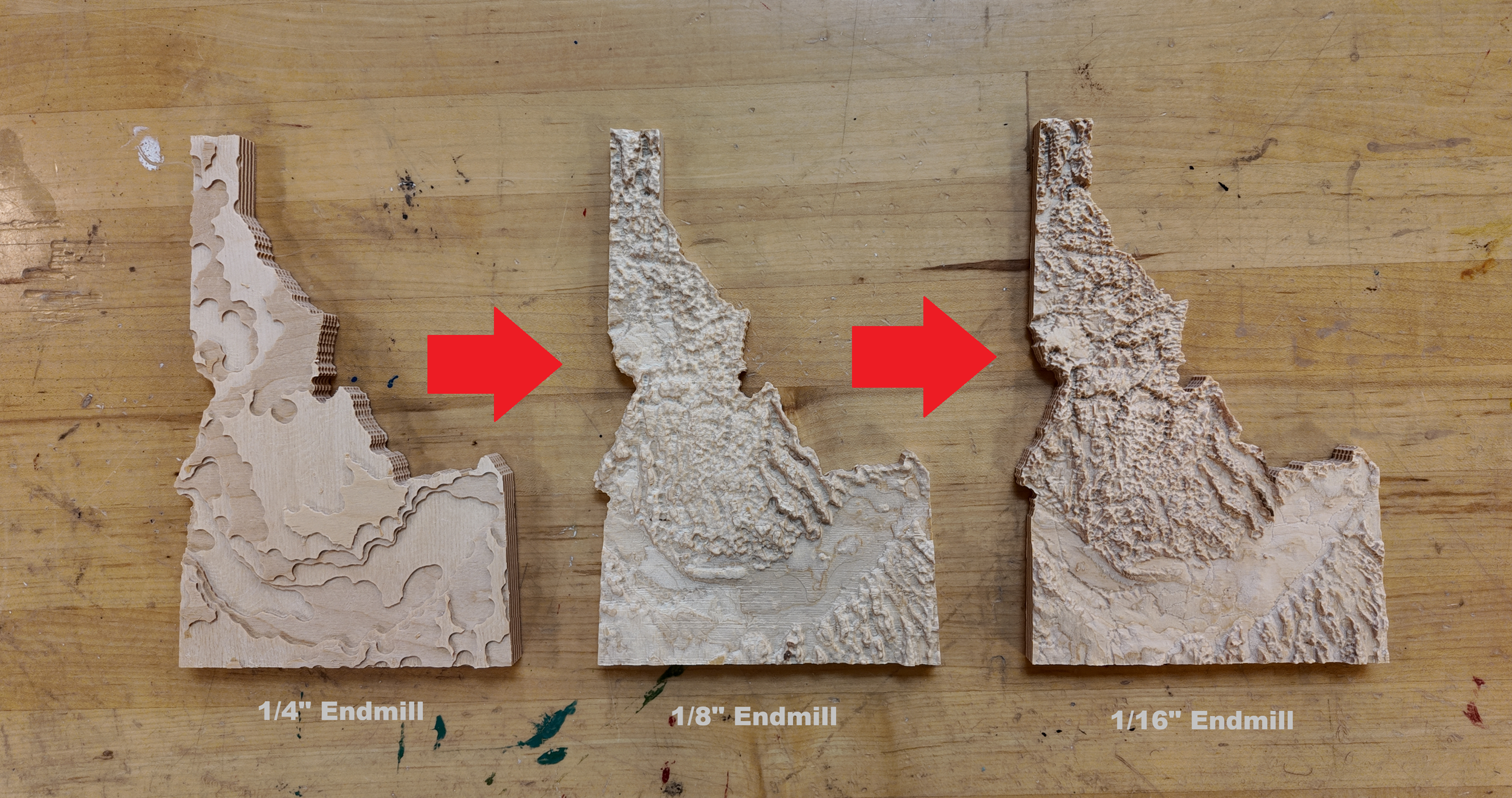
I am going to make three topographic maps (all seen above) Each with a different quality of finish.
For the First, I will just do the roughing cut with the 1/4” Endmill.
For the Second, I will use a 1/4” endmill to remove material before finishing with a 1/8”.
For the Third, I will do the same as the second except finish with a 1/16” instead of a 1/8”.
When choosing which size endmill to use for the finishing cut, choose the Largest endmill that provides the level of detail you want. This is because cutting times get exponentially longer with smaller endmills.
Note: Finishing with a 1/8” endmill took 1 hour. Finishing with a 1/16” endmill took 6 hours.
With designs where your roughing endmill leaves too much material for the small endmill to cut (ex: a ravine between mountains) you can use a third “middle ground” endmill to rough out deep pockets reducing the load on the smaller endmill. An example of this is using a 1/4” endmill to rough, then a 1/8” to rough deep areas, and then finish with a 1/16”.
A video showing the simulation for cutting the Idaho Topographic map.
One thing to note is the border I created around Idaho (seen in the video above)
I created this border because when our tapered endmill would reach the Idaho border, It would run into the stock on the side with full tool engagement.
That was the only design change made, so now we can talk about toolpaths.
Creating Toolpaths
Note: for a more comprehensive guide to creating toolpaths, reference my “CNC Machining Common Materials” Blog.
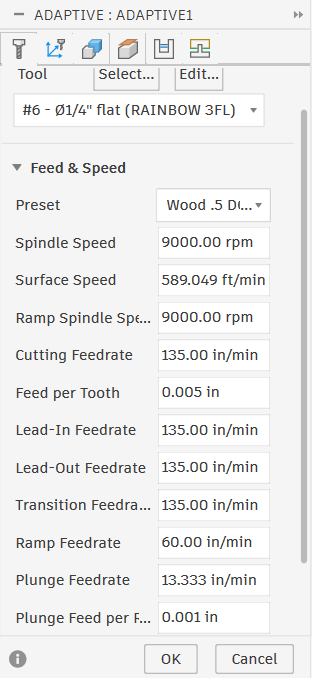
For hogging out as much material with the 1/4” endmill as possible, I decided to use a 3D Adaptive Clearing toolpath.
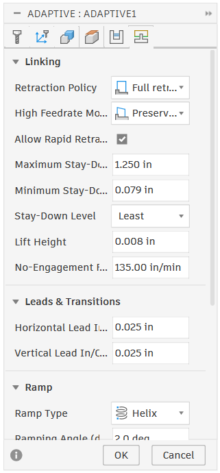
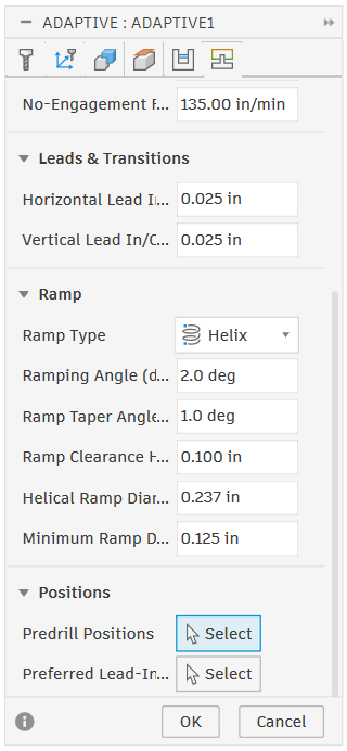
The things that differ from 2D to 3D Adaptive Clearings are:
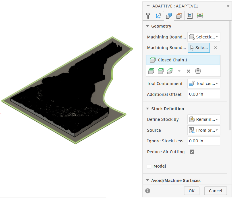
Stock Definition (Geometry)
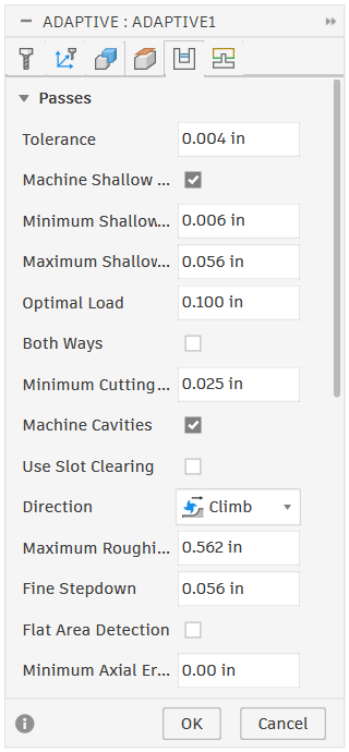
Machine Shallow Areas (Passes)
Machine Cavities (Passes)
Flat Area Detection (Passes)
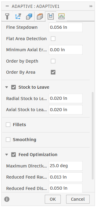
Order by Depth vs Area (Passes)
Stock Definition: Controls how Fusion generates Toolpaths regarding the Stock. This should be set to “Remaining Stock” and the source should be “From Previous Operations”. (This makes fusion remember what has already been cut in previous operations and is important as we add more toolpaths)
Machine Shallow Areas: reduces the stepdown when removing material on small slopes and hills allowing more material removal at the cost of more machining time
Machine Cavities: determines whether the machine will ramp down into pockets and holes or, if deselected, it will skip pockets entirely.
Flat Area Detection: Fusion will detect if there are flat areas in your design and create toolpaths at those levels.
Order by Depth vs Area: Changes the order in which the machine cuts areas out.
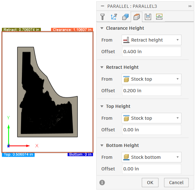
Note: When selecting your machining boundary in the geometry tab, If you select the outside contour of your part, you cannot set an offset if using center or outside “tool containment”. Otherwise the tool will run down the side and cut out the design without tabs.
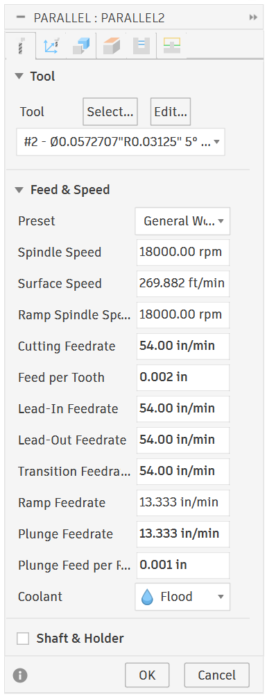
Next we have our finishing pass with a 1/8” Endmill
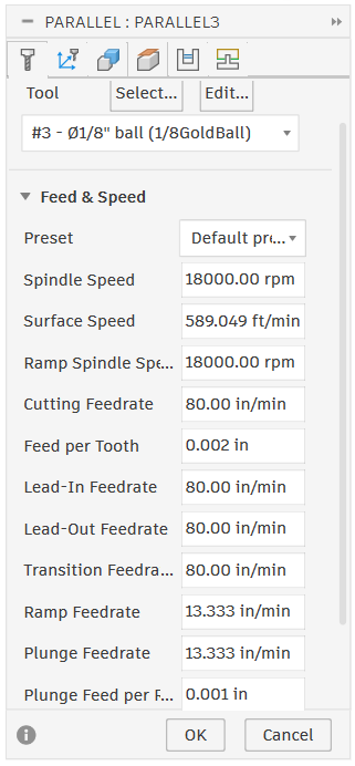
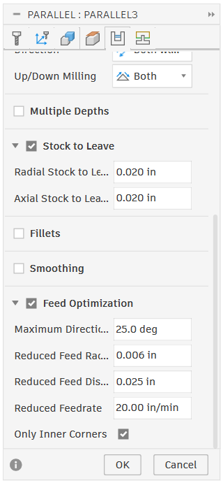
Note: The images above contain toolpaths made specifically for a roughing cut instead of a finishing pass. The only settings needed to change from a roughing to finishing pass is stepover and stock to leave. (Make the stepover 6-10% of the tool’s diameter, and leave no stock)
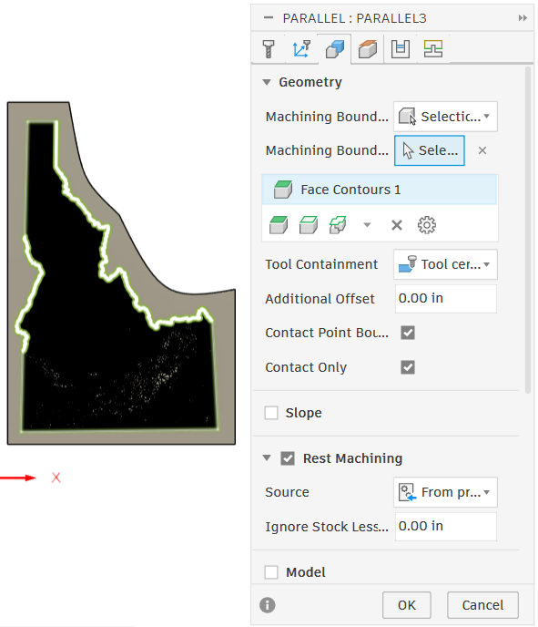
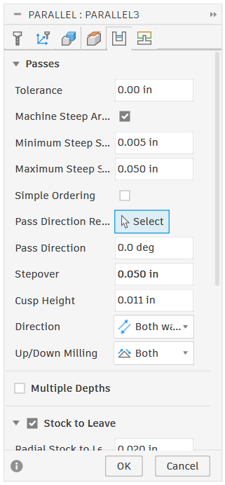
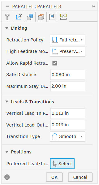
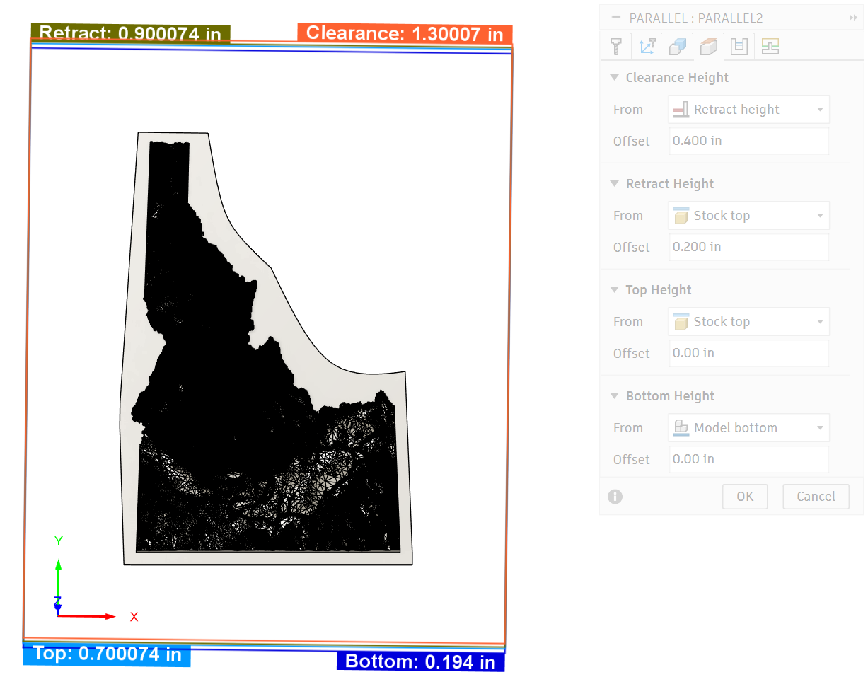
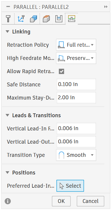
To create a finishing pass, I used a “parallel” toolpath. Parallel toolpaths follow the contour of the shape using a small stepover to slowly - and precisely - cut a nice finish surface on a part.
Parallel Toolpaths share most settings with the 3D adaptive but has some differences.
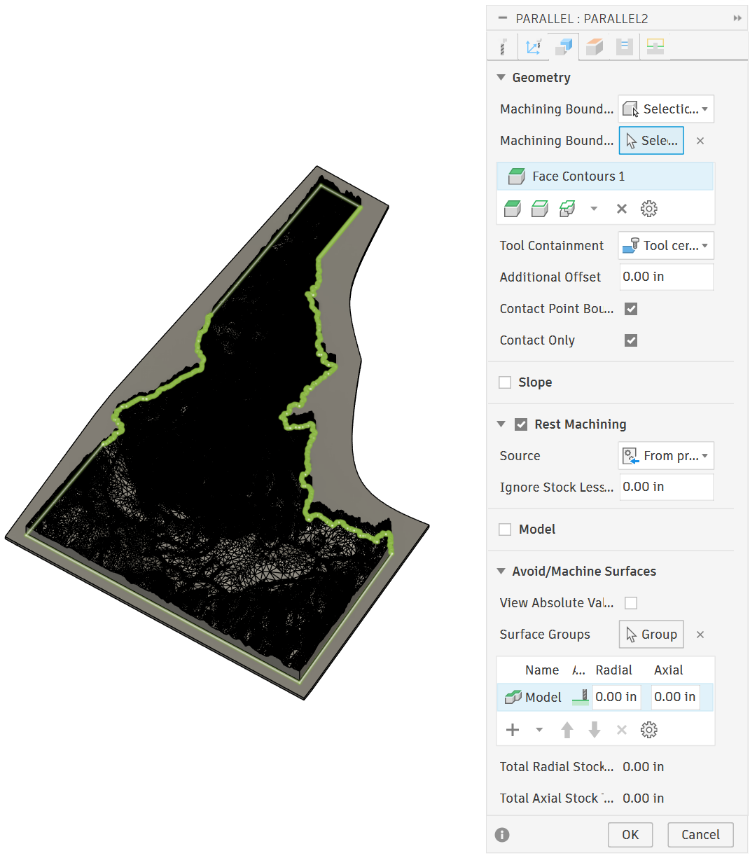
Slope (Geometry)
Rest Machining (Geometry)
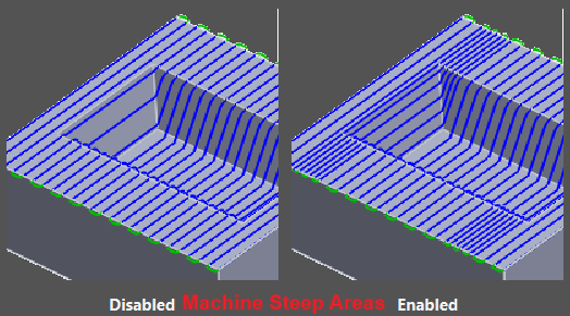
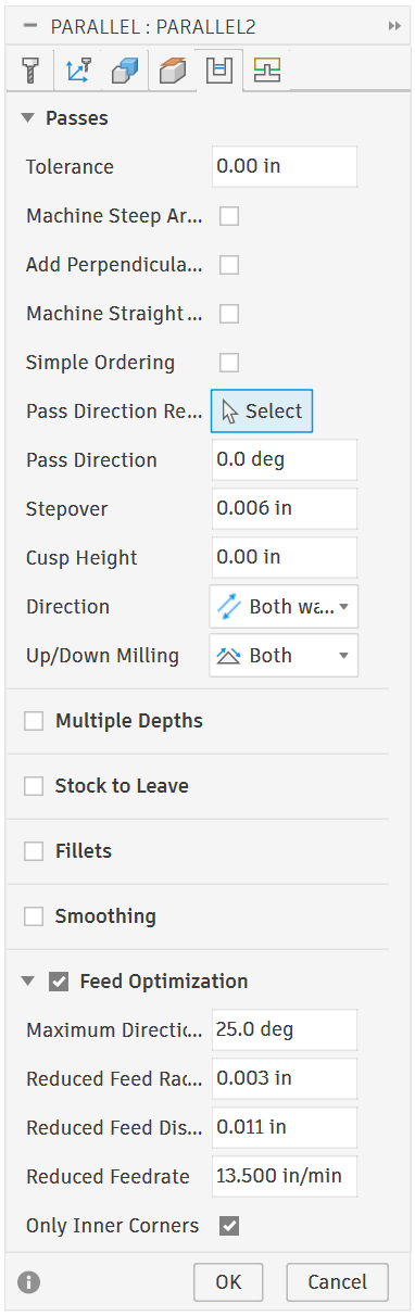
Machine Steep Areas (Passes)
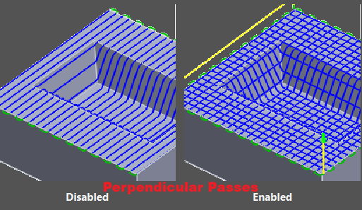
Add Perpendicular passes (Passes)
Machine Straight On (Passes)
Simple Ordering (Passes)
Slope: Allows you to specify what how steep of an angle you want to machine / avoid machining.
Rest Machining: Exact same as “Stock Definition” for 3D adaptive. REST stands for REmaining STock and will not recut anything that has already been cut by a previous operation. (“Source” should be set to “from previous operations”)
Machine Steep Areas: adds extra passes (with less stepover) to be more accurate while cutting steep areas
Add Perpendicular Passes: Cuts in both directions instead of just the x-axis. Allows for better finishes on sharp points
Machine Straight On: Auto-detects steep areas and machines perpendicular to them to leave a better finish
Simple Ordering: Changes the order the machine cuts into a simple order in the cutting direction instead of ordering by shortest distance. Can be used to avoid certain marks left by the machine but increases machining time.
Finally, we have the settings for our 1/16” Endmill
The only settings that changed between the 1/8” and 1/16” endmills is the endmill itself (under tools) and stepover (under passes).
Final Thoughts
With the toolpaths created, the only thing left is physically cutting them out on the machine. For more information of how to use the machine here at JUMP, reference my “CNC Machining Common Materials” blog.
3D machining has many useful and amazing applications from coins, tokens, and medallions to maps, molds, and more, the options are endless!
I hope this blog has taught enough to get you on your feet with CNC machining 3D objects
To everyone who read this far, thank you! Get creative and don’t be afraid to learn along the way!
Sincerely,
Jonathan Siddoway